Resultados da pesquisa pornodemcu

Este tutorial foi um dos vencedores do “Automation Contest 2017” do Instructables.com
winner at Automation Contest
Alguns meses atrás, explorei aqui como usar a Alexa, um assistente pessoal inteligente, popularizado pelo Amazon Echo e Echo-Dot, em projetos de automação residencial:

Quando o IoT encontra a Inteligência Artificial: Automação residencial com Alexa e NodeMCU

Alexa é capaz de interação de voz, reprodução de música, fazer listas de tarefas, configurar alarmes, podcasts de transmissão, reproduzir audiobooks e fornecer informações meteorológicas, de tráfego e outras informações em tempo real. A Alexa também pode controlar vários dispositivos inteligentes funcionando como um hub de automação residencial. Usaremos neste projeto, o “Echo-Dot”, que permite aos usuários ativar o dispositivo usando uma palavra de despertar, como “Alexa” ou “Computer”, como em “Star Trek !

No espaço da automação residencial, a Alexa pode interagir com vários dispositivos diferentes como Philips Hue, Belkin Wemo, SmartThings, etc. Em nosso caso, vamos emular o WeMo, usando a biblioteca fauxmoESP.

Esta é a principal diferença entre este tutorial e o anterior. A biblioteca fauxmoESP simplifica extremamente o código necessário para o desenvolvimento de projetos de automação residencial envolvendo a Alexa e o NodeMCU.

WeMo é uma série de produtos da Belkin International, Inc. que permite aos usuários controlar eletrodomésticos desde qualquer lugar. O conjunto de produtos inclui um interruptor, sensor de movimento, interruptor de luz, câmera e aplicativo.

O WeMo Switch (nosso caso aqui) pode ser conectado a qualquer tomada doméstica, a qual pode ser controlada a partir de um smartphone iOS ou Android o qual executará o aplicativo WeMo, via rede doméstica WiFi ou rede celular. Nós emularemos este dispositivo, mas seu controle será obtido por voz via o Echo-Dot.

O diagrama de blocos abaixo mostra o que será desenvolvido em nosso projeto:

O vídeo abaixo mostra como o projeto ficará no final:


Continue lendo…

Alexa – NodeMCU: WeMo Emulation Made Simple

22 22-03:00 agosto 22-03:00 2017
A few months ago, I have explored here how to use Alexa, an intelligent personal assistant made popular by the Amazon Echo and Echo-Dot, in Home Automation projects:

When IoT Meets AI: Home Automation With Alexa and NodeMCU

Alexa is capable of voice interaction, music playback, making to-do lists, setting alarms, streaming podcasts, playing audiobooks, and providing weather, traffic, and other real time information. Alexa can also control several smart devices using itself as a home automation hub. We will use on this project, the “Echo-Dot”, that allows users to activate the device using a wake-word, such as “Alexa” or “Computer”, as in “Star Trek!.

In the home automation space, Alexa can interact with several different devices as Philips Hue, Belkin Wemo, SmartThings, etc. In our case, we will emulate the WeMo, using the fauxmoESP library,

Here is the main difference between this tutorial and my previous one. The fauxmoESP library simplifies extremely the code needed to develop home automation projects.

WeMo is a series of products from Belkin International, Inc. that enables users to control home electronics from anywhere. The product suite includes a switch, motion sensor, Insight Switch, light switch, camera, and app. The WeMo Switch (our case here) can be plugged into any home outlet, which can then be controlled from an iOS or Android smartphone running the WeMo App, via home WiFi or mobile phone network.

The below block diagram shows what will be developed on our project:

The below video, shows how the project will look like at the end:

Step 1: Bill of Material (BoM)

(All values are referenced in USD)

  1. NodeMCU ESP8266-12E ($8.79)
  2. Echo Dot (2nd Generation) – Black ($49.99)
  3. 2 X Mini BreadBoard ($1.00)
  4. 4-Channel Relay Module ($8.49)
  5. Male-Female Dupont Cables ($1.00)
  6. External 5V power Supply or battery

Step 2: WeMo Emulation – the FauxmoESP Library

This tutorial is based on the great open source lib & example developed by Xosé Perez (Tinkerman). See his original post here: Emulate a WeMo device with ESP8266. Tinkerman based its work on Python example code developed by Maker Musings.

fauxmoESP is a library for ESP8266-based devices that emulates a Belkin WeMo device and thus allows you to control them using this protocol, in particular from Alexa-powered devices like the Amazon Echo or the Dot.

The library can be found on Xose Perez’s BitBucket: fauxmoESP

1. fauxmoESP Library ZIP

In order to run it in your code, you will also need 2 more libraries by Hristo Gochkov:

2. ESPAsyncTCP

3. ESPAsyncWebServer

So, Go to your Arduino IDE and install the 3 above libraries under your Arduino/Library directory.

Some Technical stuff (optional):

If you are interested in understanding more deeply what’s going on, read the article: HOW TO MAKE AMAZON ECHO CONTROL FAKE WEMO DEVICES, written by Rick Osgut where you can learn the basis of WeMo emulation.

WeMo Emulation - the FauxmoESP Library

The WeMo devices use UPnP to perform certain functions over the network. The device detection function starts out with the Echo or Dot (in our case here, the Dot) searching for WeMo devices using UPnP. The device then responds to the Dot with the device’s URL using HTTP over UDP. The Dot then requests the device’s description using that HTTP URL. The description is then returned as an HTTP response.

The actual “on/off” functionality of the WeMo devices is simpler since the Dot already knows about the device. The Dot simply connects to the WeMo over the HTTP interface and issues a “SetBinaryState” command. The WeMo then obliges and returns a confirmation via HTTP (see the Echo/Dot Communication diagram above).

Step 3: Creating Our WeMo Devices With NodeMCU

Creating Our WeMo Devices With NodeMCU

Let’s connect a 4 Channel relay module to control 2 lamps and 2 outlets as shown in above diagram.

We will create 4 “single smart devices”:

  • Light1 ==> Relay 1 ==> NodeMCU D5
  • Light2 ==> Relay 3 ==> NodeMCU D7
  • Outlet1 ==> Relay 2 ==> NodeMCU D6
  • Outlet2 ==> Relay 4 ==> NodeMCU D8

and 3 groups of combined devices:

  • All Devices (Light1, Light2, Outlet1 and Outlet2)
  • Living Room (Light1 and Outlet1)
  • Bed Room (Light2 and Outlet2)

Download and open the file NODEMCU_ALEXA_WeMos_4X_Fauxmo_EXT.inofrom my GitHub and change the dummy wifi credentials, with your own:

/* Network credentials */
#define WIFI_SSID "YOUR SSID HERE" 
#define WIFI_PASS "YOUR PASSWORD HERE"

Confirm that you have properly defined the pins where the relays are connect:

/* Set Relay Pins */
#define RELAY_1 D5 
#define RELAY_2 D6 
#define RELAY_3 D7 
#define RELAY_4 D8

Now, we must define the “name” as our devices will be understood by Alexa:

// Device Names for Simulated Wemo switches
fauxmo.addDevice("Light One"); 
fauxmo.addDevice("Light Two"); 
fauxmo.addDevice("Outlet One"); 
fauxmo.addDevice("Outlet Two"); 
fauxmo.addDevice("Bed Room"); 
fauxmo.addDevice("Living Room"); 
fauxmo.addDevice("All Devices");

And, we must at setup(), define the “callback” function:

fauxmo.onMessage(callback);

The loop() should be:

void loop() 
{ 
  fauxmo.handle(); 
}

The callback function should be developed as below (this is only for Light1):

/* ----------------------------------------------------------------
   Device Callback 
-------------------------------------------------------------------*/ 
void callback(uint8_t device_id, const char* device_name, bool state) 
{ 
  Serial.print("Device "); 
  Serial.print(device_name); 
  Serial.print(" state: "); 
  if (state) 
  { 
    Serial.println("ON"); 
  } 
  else 
  { 
    Serial.println("OFF"); 
  } 

  //Switching action on detection of device name 
   
  if ( (strcmp(device_name, "Light One") == 0) ) 
  { 
    if (!state) 
    { 
      digitalWrite(RELAY_1, HIGH); 
    } 
    else 
    { 
      digitalWrite(RELAY_1, LOW); 
    } 
  }
  
  ....
}

Note that I used “!state” inside the “if statement”, because the 4 channel relays use reversed logic for activation.

On the Serial monitor you can see the messages exchanged:

[WIFI] Connecting to ROVAI TIMECAP 
............................. ==> CONNECTED! 
[WIFI] STATION Mode, SSID: ROVAI TIMECAP, IP address: 10.0.1.36

Now, let’s ask Alexa to find your device. There are 2 methods to do it:

  1. Using the Alexa App in your Smartphone
  2. Asking Alexa to do it directly using voice command, like: “Alexa (in our case “Computer”), Find connected devices” as shown in the video below:

Once Alexa has discovery your device, you can give her voice commands as shown below:

The below screenshot shows the Serial monitor response.

Serial Monitor.png

Step 4: Conclusion

As always, I hope this project can help others find their way in the exciting world of electronics and IoT!


Please visit my GitHub for updated files:

Home-Automation-with-Alexa-and-NodeMCU/tree/master/Version_FauxmoESP

Saludos from the south of the world!

See you in my next tutorial!

Thank you

Marcelo

Neste tutorial, exploraremos como controlar um servo através da Internet. Para isso, lançaremos mão de uma importante dupla de dispositivos no mundo do IoT:

o NodeMCU ESP12-E e o Blynk.

Começaremos por aprender como conectar um servo com o NodeMCU, como controlá-lo localmente com um potenciômetro, como ver sua posição em um display e finalmente como controlá-lo através da internet usando um smartphone.

O diagrama de blocos abaixo nos dá uma visão geral do projeto final.

Servo Control Block Diagram


E o vídeo, mostrará o projeto funcionando:

Continue lendo…

In this simple tutorial, we will explore how to control a servo over the internet. For that, we will use a great couple of devices, the NodeMCU ESP12-E and a Blynk App.
We will start learning how to connect the servo with the NodeMCU, knowing how to control it locally with a potentiometer, how to see its position on an OLED display and finally how to control it over the internet using a smartphone.
The Block diagram below gives us an overview of the final project.
Servo Control Block Diagram

Also, the bellow video shows the final project working:

Step 2: Connecting the Servo and Potentiometer

IMG_1573.jpg

The first thing that we will do, is to setup the NodeMCU to handle the 180o Servo, controlling it thru a 10K ohm potentiometer.

Servo-Pot Block Diagram

Take care that the NodeMCU is powered with 5V, but all its GPIOs work with a 3.3V level.

Let’s split the Breadboard power raids, one for 5V and the other for 3.3V. For that, we will use the breadboard Power Supply as the one shown in the electrical diagram.

Servo Circuit 1


NOTE: During the development phase, when your PC is connected to NodeMCUvia the USB port, you do not need connecting Vin to +5V (red wire at the diagram), once the power will be provided by your computer. Leave it disconnected.

For Servo operation, we will use the servo.h library:

#include <Servo.h>   // Include the library
Servo servo1;        // Create the Servo and name it "servo1"
#define servo1Pin D2 // Define the NodeMCU pin to attach the Servo

During setup(), the servo1 must be initiated:

servo1.attach(servo1Pin);

The 10K potentiometer will work as a voltage divisor, changing the analog input level on NodeMCU (A0) from 0 to 3.3V. Internally, the 10 bits ADC (Analog-Digital converter) will generate a digital value (from 0 to 1023), the PotReading, equivalent to the analog voltage input.

PotReading = analogRead(A0);

We should “map” this digital value, in order that the Pulse Width Modulated (PWM) digital output of pin D2, will vary from 0 to 180 (servo1Angle).

servo1Angle = map(PotReading, 0, 1023, 0, 180);

With this signal, the servo will turn from 0 to 180 degree, using the bellow command:

servo1.write(servo1Angle); 

The position value that is sent to Servo will be displayed during this test phase on Serial Monitor:

Serial.println(servo1Angle);

The full code for Servo’s tests can be downloaded from my GitHub:

NodeMCU_Servo_Control_Test

The below video shows the servo test:

Step 3: Let’s Display!

Let's Display!

It is OK during tests, to use the Serial Monitor, but what’s happen when you are using your prototypes far from your PC in a stand alone mode? For that, let’s install an OLED display, our old friend, SSD1306, wich main characteristics are:

  • Display size: 0.96″
  • I2C IIC SPI Serial
  • 128X64
  • White OLED LCD LED

Connect the OLED pins to the NodeMCU, as described bellow and shown at above electrical diagram:

  • SDA ==> D1 (5)
  • SCL* ==> D2 (4) * Also you can find “SDC” in the text
  • VCC ==> The SSD1306 can be powered with both 5V or 3.3V (in our case, 3.3V)
  • GND ==> GND

Once we have connected the display, let’s download and install its library on our Arduino IDE: the “ESP8266 OLED Driver for SSD1306 display” developed by Daniel Eichhorn (Make sure that you use Version 3.0.0 or bigger!).

Bellow the library that must be downloaded and installed on your Arduino IDE:

https://github.com/squix78/esp8266-oled-ssd1306

Once you restarted the IDE, the library should be already installed.

The library supports I2C protocol to access the OLED display using the built-in Wire.h library:

#include <Wire.h>   
#include "SSD1306.h"
SSD1306  display(ADDRESS, SDA, SDC);

Let’s list some important API that will be used with our OLED display. The complete list can be found at the GITHub provided above.

A. Display Control:

void init(); // Initialise the display
void displayOn(void); // Turn the display on
void displayOff(void); // Turn the display offs
void clear(void); // Clear the local pixel buffer
void flipScreenVertically(); // Turn the display upside down

B. Text Operations:

void drawString(int16_t x, int16_t y, String text); // (xpos, ypos, "Text")<br><p>void setFont(const char* fontData);  // Sets the current font. </p>// Available default fonts: ArialMT_Plain_10, ArialMT_Plain_16, ArialMT_Plain_24

IMG_1582.jpg

Once the both the OLED itself and its Library are installed, let’s write a simple program to test it. Enter with bellow code on your IDE, the result should be a display as shown in the above photo:

/*NodeMCU */
#include <ESP8266WiFi.h>

/* OLED */
#include "SSD1306Wire.h"
#include "Wire.h"
const int I2C_DISPLAY_ADDRESS = 0x3c;
const int SDA_PIN = 0;
const int SCL_PIN = 2;
SSD1306Wire     display(I2C_DISPLAY_ADDRESS, SDA_PIN, SCL_PIN);

void setup () 
{
  Serial.begin(115200); 
  displaySetup();
}

void loop() 
{ 
}

/* Initiate and display setup data on OLED */
void displaySetup()
{
  display.init();         // initialize display
  display.clear();        // Clear display
  display.display();      // Put data on display
  
  Serial.println("Initiating Display Test");
  
  display.setFont(ArialMT_Plain_24);
  display.drawString(30, 0, "OLED");  // (xpos, ypos, "Text")
  display.setFont(ArialMT_Plain_16);
  display.drawString(18, 29, "Test initiated");
  display.setFont(ArialMT_Plain_10);
  display.drawString(10, 52, "Serial BaudRate:");
  display.drawString(90, 52, String(11500));
  display.display();  // Put data on display
  delay (3000);
}

The above program can be downloaded from my GitHub:

NodeMCU_OLED_Test

Step 4: Showing the Servo Position in the OLED Display

Showing the Servo Position in the OLED Display

Now let’s “merge” the previous 2 codes, so we can not only control the servo position using the potentiometer but also see its position in the OLED display.

The code can be downloaded from my GitHub:

NodeMCU_Servo_Control_Test_OLED

And the result can be verified on the video:

Step 5: Creating a Blynk App to Control the Servo

IMG_1593.jpg

Basically, we will need to change our previous code to include the Blynk part of it:

#include <BlynkSimpleEsp8266.h>
char ssid [] = "YOUR SSID";
char pass [] = "YOUR PASSWORD";
char auth [] = "YOUR AUTH TOKEN"; // Servo Control Project

/* Reads slider in the Blynk app and writes the value to "potReading" variable */
BLYNK_WRITE(V0) 
{
  potReading = param.asInt();
}

/* Display servo position on Blynk app */
BLYNK_READ(V1) 
{
  Blynk.virtualWrite(V1, servo1Angle);
}

void setup () 
{
  Blynk.begin(auth, ssid, pass);
}

void loop() 
{
  Blynk.run();
}

So, we must define a virtual pin V0, where Blynk will “Write” a servo position, the same way as we did with the potentiometer. On Blynk App, we will use a “Slider” (with output defined from 0 to 1023) to command the servo position.

Another virtual pin, V1, will be used to “Read” the servo position, same as we do with the OLED. On Blynk App, we will use a “Display” (with output defined from 0 to 180) to show the servo position.

Creating a Blynk App to Control the Servo

The above foto show the App screens.

You can download the complete program from GitHub:

NodeMCU_Servo_Ctrl_Blynk_EXT

Step 6: Conclusion

As always, I hope this project can help others find their way in the exciting world of electronics, robotics, and IoT!
Please visit my GitHub for updated files: IoT-Servo-Control
For more projects, please visit my blog:  MJRoBot.org
Saludos from the south of the world!
See you in my next post!
Thank you
Marcelo

WiFi Voice Controlled Robot With NodeMCU

3 03-03:00 abril 03-03:00 2017

On my last tutorial, Voice Activated Control With Android and NodeMCU we explored how to develop our own App on an Android smartphone to control locally (using buttons or voice) smart home devices. But How about starting from there and instead home devices we control motors? And still better, how about having those motors driving a differential robot? That is exactly what we will develop here, a WiFi Voice Controlled Robot using as a controller, our old bud NodeMCU!

The block diagram shows what will be done in general:

WiFi_Robot_Block_Diagram

and the movie below shows the final project working:

Please consider that one of my motors was with very little torque. Spite that the result seems rare, the project was a success. As soon I change the motor I will update the video. Thanks.

Step 1: Bill of Material (BoM)

All values are referencial in USD

  1. NodeMCU ESP8266-12E ($8.79)
  2. 400-point Experiment Breadboard Breadboard ($ 4.97)
  3. H-Bridge L293D ($2.17)
  4. Motor Robot Car Chassis Kit ($13.00)
  5. Male-Female Dupont Cables ($1.00)
  6. Portable Charger 5VDC 3000mAh Power Bank ($10.00)
  7. External 9VDC Battery

….. and of course, any Android Smartphone or Tablet!

Step 2: The H-Bridge L293D

The H-Bridge L293D

In order to drive the motors we will use the L293D a Quadruple Half-H Drivers H-Bridge.

According its Datasheet, The L293 and L293D devices are quadruple high-current half-H drivers. The L293 is designed to provide bidirectional drive currents of up to 1 A at voltages from 4.5 V to 36 V. The L293D is designed to provide bidirectional drive currents of up to 600-mA at voltages from 4.5 V to 36 V. Both devices are solenoids, DC and bipolar stepping motors, as well as supply applications.

We will use the IC directly with the NodeMCU, not using a shield, that is also common.

Our Robot has two wheels, that are driven by 2 DC motors:

  • LEFT Motor
  • RIGHT Motor

We will connect the motors to our H-Bridge as shown at above diagram. The NodeMCU will have 6 GPIOs that will command those motors.

int rightMotor2 = 13;   // D7 - right Motor -
int rightMotor1 = 15;   // D8 - right Motor +
int leftMotor2 = 0;     // D3 - left Motor - 
int leftMotor1 = 2;     // D4 - left Motor +
int eneLeftMotor = 12;  // D6 - enable Motor Left
int eneRightMotor = 14; // D5 - enable Motor Right

For example, to drive LEFT motor FORWARD you must put:

  • HIGH at pin D4 (left Motor +) and
  • LOW at pin D3 (left Motor -)

For the RIGHT Motor you must do the opposite:

  • HIGH at pin D8 (right Motor +) and
  • LOW at pin D7 (left Motor -)

Due the way that my motors are assembly and the robot moves, the above combination will drive both motors in the same direction pushing the Robot forward.

Robot direction.jpg

Look the above diagram that define how the robot will move. This is important for proper definition of your variables.

To control the H-Bridge properly, you must also working with the enable pins. The above combination that will drive robot forward will only work if the enable pins (eneLeftMotor and eneRightMotor) are both in HIGH. You can connect those L293D pins (1 and 9) directly to +VCC and forget them. I do not like it, because for a full stop, those pins are better to be in LOW. Also, associating the enable pins to a NodeMCU PWM digital outputs will allow you to control motor speed (using digital values as HIGH and LOW, will set the speed to MAX and ZERO, respectively).

So, for creating a function to drive our robot forward, we should pu together a code like this:

void forwardMotor(void)   
{
  digitalWrite(eneLeftMotor,HIGH);
  digitalWrite(eneRightMotor,HIGH);
    
  digitalWrite(leftMotor1,HIGH);
  digitalWrite(leftMotor2,LOW);
  digitalWrite(rightMotor1,HIGH);
  digitalWrite(rightMotor2,LOW);
}

Step 3: Moving the Robot Around

L293D.jpg

In the previous step we learned how we can move the robot forward, let’s think now how to move it around.

We will define 5 possible commands:

  1. STOP
  2. Turn to LEFT
  3. Turn to RIGHT
  4. REVERSE
  5. FORWARD

The first command “STOP” is simple to accomplish. All H-Bridge inputs must be LOW, this way the motors will not be moving:

void stopMotor(void)   
{
  digitalWrite(eneLeftMotor,LOW);
  digitalWrite(eneRightMotor,LOW);

  digitalWrite(leftMotor1,LOW);
  digitalWrite(leftMotor2,LOW);
  digitalWrite(rightMotor1,LOW);
  digitalWrite(rightMotor2,LOW);
}

The same way let’s think about turn the robot to one direction, let’s say LEFT. Consider that the robot is going Forward, if we want to turn to left, we can have two situations:

  1. Stop LEFT motor and keep RIGHT going FW
  2. Reverse LEFT Motor and keep RIGHT going FW

At first situation, the robot will do an arc trajectory to the left. On the second, the robot will turn in its axy to the left. We will implement the second one.

void leftMotor(void)   
{
  digitalWrite(eneLeftMotor,HIGH);
  digitalWrite(eneRightMotor,HIGH); 
  
  digitalWrite(leftMotor1,LOW);
  digitalWrite(leftMotor2,HIGH);
  digitalWrite(rightMotor1,HIGH);
  digitalWrite(rightMotor2,LOW);
}

The remain commands follow the same logic.

Moving the Robot Around

The above table resume the 5 commands.

Step 4: Completing the HW

Completing the HW

Follow the above diagram and complete the Robot HW.

You can make simple tests to see you your code are OK.

It’s good for simplify tests, to introduce a “Button” for starting your robot. We will install it at NodeMCU port D0 as shown at diagram.

You can use the below program for testing your robot movements:

// Set Motor Control Pins
int rightMotor2 = 13;    // D7 - right Motor -
int rightMotor1 = 15;    // D8 - right Motor +
int leftMotor2 = 0;    // D3 - left Motor - 
int leftMotor1 = 2;    // D4 - left Motor +
int eneLeftMotor = 12;  // D6 - enable Mortor Left
int eneRightMotor = 14; // D5 - enable Mortor Right

int buttonPin = 16; // D0

void setup()
{
  Serial.begin(115200);

  pinMode(buttonPin, INPUT_PULLUP);
  pinMode(eneLeftMotor, OUTPUT); 
  pinMode(eneRightMotor, OUTPUT); 
  pinMode(leftMotor1, OUTPUT); 
  pinMode(leftMotor2, OUTPUT);  
  pinMode(rightMotor1, OUTPUT);  
  pinMode(rightMotor2, OUTPUT);  

  digitalWrite(eneLeftMotor,LOW);
  digitalWrite(eneRightMotor,LOW);
  digitalWrite(leftMotor1,LOW);
  digitalWrite(leftMotor2,LOW);
  digitalWrite(rightMotor1,LOW);
  digitalWrite(rightMotor2,LOW);
      
  while (digitalRead(buttonPin))  // Wait for button to be pressed to move on 
  {  
  }
}

void loop()
{
  forwardMotor();
  delay (5000);
  stopMotor();
  delay (200);
  leftMotor();
  delay (3000);
  stopMotor();
  delay (200);
  forwardMotor();
  delay (5000);
  stopMotor();
  delay (200);
  rightMotor();
  delay (3000);
  stopMotor();
  delay (200);
  reverseMotor();
  delay (5000);
  stopMotor();
  delay (200);
} 

/* command motor forward */
void forwardMotor(void)   
{
  digitalWrite(eneLeftMotor,HIGH);
  digitalWrite(eneRightMotor,HIGH);
    
  digitalWrite(leftMotor1,HIGH);
  digitalWrite(leftMotor2,LOW);
  digitalWrite(rightMotor1,HIGH);
  digitalWrite(rightMotor2,LOW);
}

/* command motor backward */
void reverseMotor(void)   
{
  digitalWrite(eneLeftMotor,HIGH);
  digitalWrite(eneRightMotor,HIGH);
  
  digitalWrite(leftMotor1,LOW);
  digitalWrite(leftMotor2,HIGH);
  digitalWrite(rightMotor1,LOW);
  digitalWrite(rightMotor2,HIGH);
}

/* command motor turn left */
void leftMotor(void)   
{
  digitalWrite(eneLeftMotor,HIGH);
  digitalWrite(eneRightMotor,HIGH); 
  
  digitalWrite(leftMotor1,LOW);
  digitalWrite(leftMotor2,HIGH);
  digitalWrite(rightMotor1,HIGH);
  digitalWrite(rightMotor2,LOW);
}

/* command motor turn right */
void rightMotor(void)   
{
  digitalWrite(eneLeftMotor,HIGH);
  digitalWrite(eneRightMotor,HIGH);
  
  digitalWrite(leftMotor1,HIGH);
  digitalWrite(leftMotor2,LOW);
  digitalWrite(rightMotor1,LOW);
  digitalWrite(rightMotor2,HIGH);
}

/* command motor stop */
void stopMotor(void)   
{
  digitalWrite(eneLeftMotor,LOW);
  digitalWrite(eneRightMotor,LOW);

  digitalWrite(leftMotor1,LOW);
  digitalWrite(leftMotor2,LOW);
  digitalWrite(rightMotor1,LOW);
  digitalWrite(rightMotor2,LOW);
}

When you press the button, the robot will start doing the movements defined on loop(). it will continuous until you press “Reset” on NodeMCU. Pressing the button, the cycle repeats.

The code can be download from my GitHub:

WiFi_Robot_NodeMCU_Android_Voice_Motor_tests

Step 5: Assembling the Robot Body

  1. Take the Kit (Chassis, 2 Wheels, 2 DC Motors, 1 coaster
  2. Take out the Chassis cover (or leave it)
  3. Solder 2 10 cm wires (Red and Black) at each motor
  4. Fixed the motors at chassis
  5. Assembly the coaster
  6. Joint the motor wires to electronics (L293D)
  7. Fix the 9V battery on the chassis
  8. Fix the 5V battery under the chassis

Body Final

Step 6: Connecting the NodeMCU to Local WiFi

Let’s connect the NodeMCU to our local WiFi and check its IP address. For that, let’s use the below small program:

#include <ESP8266WiFi.h>
WiFiClient client;
WiFiServer server(80);
const char* ssid = "YOUR SSID";
const char* password = "YOUR PASSWORD";

void setup() 
{
  Serial.begin(115200);
  connectWiFi();
  server.begin();
}

void loop() 
{
}

/* connecting WiFi */
void connectWiFi()
{
  Serial.println("Connecting to WIFI");
  WiFi.begin(ssid, password);
  while ((!(WiFi.status() == WL_CONNECTED)))
  {
    delay(300);
    Serial.print("..");
  }
  Serial.println("");
  Serial.println("WiFi connected");
  Serial.println("NodeMCU Local IP is : ");
  Serial.print((WiFi.localIP()));
}

On the Serial monitor you can see its IP Address.

Connecting the NodeMCU to Local WiFi

Take note of it. We will need it to connect the Android App.

The code can be download from my GitHub:

NodeMCU_Connection_Test_EXT

Step 7: Completing the Code

To move our Robot, we need to receive commands from the Android device. for that a command variable will be defined:

String  command ="";

So, for example, If the Android App send as a command: “forward”, the robot must move forward:

if (command == "forward")
{
  forwardMotor();
}

The same must be done for all possible commands received.

Download the complete code: WiFi_Robot_NodeMCU_Android_Voice_EXT from my GitHub.

Change the dummy wifi credentials, with your own:

const char* ssid = "YOUR SSID";
const char* password = "YOUR PASSWORD";

Upload the code to your NodeMCU and that’s it! You can check on Serial Monitor if the program is running, but, noting more. Let the program run for testing of your app on next step.

Step 8: The Android App: “Designer Tab”

The Android App: "Designer Tab"

We will use the MIT App Inventor to develop our Android App.

Main Components on Screen 1 (see above photo):

  • User Interface:
    • Input of IP Address
      • TextBox named “IP_Address”
    • 5 Command Buttons:
      • forward
      • reverse
      • right
      • left
      • stop
    • Voice Input Button
      • Voice_Input
  • Non Visible Components:
    • Web1
    • SpeachRecognizer1
    • TextToSpeach1
  • Other:
    • Text Box:
      • Speach_To_Text
    • Label:
      • Comm_Status

                  Screenshot_2017-04-02-14-36-34

Step 9: The Android App: Buttons

The Android App: Buttons

We must at Blocks tabs, create 5 Buttons. All of them will follow the structure of the one shown at the photo.

This button block is called when the Forward Button (“UP”) is pressed:

  • When forward.Click

For example, when you click on Button forward, 3 actions will be performed:

  • A command will be send on the format: http:/ip_address*/forward
  • An “echo” on the same format is expected
  • A sound “message” will be read by the App: in the case: “forward”

* The IP_Address will be the one that you enter on Screen 1. The default is 10.1.0.3, so the real message would be: http:/10.0.1.3/forward

You can use any message you want, or even took this block out. It is optional for the project.

Step 10: The Android App: Voice Recognition

The Android App: Voice Recognition

The above blocks show the voice recognition code for our App.

Note that, for any voice command entered, the result will be a lower case command. This will facilitate the voice recognition decoding on NodeMCU.

For example, if you want to move your robot forward, a word or sentence must be sent to be exactly recognized by NodeMCU code. I will send a command in Portuguese (my language), but you must send it on your own language (the one that is set-up on your Android device), and change the NodeMCU code properly. At bellow example, The code would recognize any one of the words: “forward”, “frente” or ä frente”

if (command == "forward" || command == "frente" || command == "a frente")  
{
  forwardMotor();
}

So, when I say “forward”, the App will send for example: http:/10.0.1.10/forward and the NodeMCU will take what is received after the “/”, that is a command “forward”. As we saw above, with this command, the function forwardMotor() will be called.

Step 11: The Android App: Error Manipulation

The Android App: Error Manipulation

If an error occur, for example when you say a voice command not recognized by the NodeMCU, the above block will write the error details on the last line (Comm_Status) of the App as shown below:

Screenshot_2017-04-02-14-36-50

Step 12: Final Test

Final Test

You can create your App step by step as shown on the previous steps or upload my complete project (.aia) at MIT App Inventor modifying it for your needs. Also If you do not have experience on developing Android apps, you can execute the .apk file directly on your Android device.

Both, the .aia and .apk files can be downloaded from my GitHub:

WiFi_Voice_Robot_Ctrl_V2.aia

WiFi_Voice_Robot_Ctrl_V2.apk

Below video show some motor tests with the App:

Step 13: Conclusion

Conclusion

As always, I hope this project can help others find their way in the exciting world of electronics, robotics and IoT!

Please visit my GitHub for updated files:

WiFi-Voice-Controlled-Robot

For more projects, please visit my blog: MJRoBot.org

Saludos from the south of the world!

See you at my next instructable!

Thank you

Marcelo

Em meu último tutorial: Quando o IoT encontra a Inteligência Artificial: Automação residencial com Alexa e NodeMCU exploramos como equipamentos ativados por voz como o Amazon Echo-Dot utilizando-se de um serviço da web (como o “Alexa”) podem controlar “dispositivos inteligentes” em nossas casas. Neste novo tutorial faremos o mesmo,  porém  em vez de usar o Alexa desenvolveremos nossa própria App em um smartphone Android controlando, tanto com botões quanto por voz, nossos dispositivos domésticos.

O diagrama de blocos nos dá uma geral do que pretendemos desenvolver:

Block Diagram.jpg

e o filme nos mostra como ficará o projeto final:

Continue lendo…

Voice Activated Control With Android and NodeMCU

29 29-03:00 março 29-03:00 2017


On my last tutorial, When IoT Meets AI: Home Automation With Alexa and NodeMCU we explored how to have voice activated devices as the Amazon Echo-Dot using a web service (like “Alexa”) can control “smart switches” on our homes. Here we will do the same, but instead of using Alexa, we will develop our own App on an Android smartphone to control locally (using buttons or voice), our home devices.

The block diagram shows what will be done in general:

Block Diagram.jpg

and the movie shows the final project working:

Step 1: Bill of Material (BoM)

All values are referencial in USD

  1. NodeMCU ESP8266-12E ($8.79)
  2. Mini BreadBoard ($1.00)
  3. 400-point Experiment Breadboard Breadboard ($ 4.97)
  4. 4-Channel Relay Module ($8.49)
  5. LEDs (Red, Yellow, Blue and Green) ($1.00)
  6. 4 x Resistor (220 ohm)
  7. Male-Female Dupont Cables ($1.00)
  8. External 5V power Supply or battery

….. and of course, any Android Smartphone or Tablet!

Step 2: Connecting the NodeMCU to Local WiFi

Let’s connect the NodeMCU to our local WiFi and check its IP address. For that, let’s use the below small program, that is part of final project:
#include <ESP8266WiFi.h>
WiFiClient client;
WiFiServer server(80);
const char* ssid = "YOUR SSID";
const char* password = "YOUR PASSWORD";

void setup() 
{
  Serial.begin(115200);
  connectWiFi();
  server.begin();
}

void loop() 
{
}

/* connecting WiFi */
void connectWiFi()
{
  Serial.println("Connecting to WIFI");
  WiFi.begin(ssid, password);
  while ((!(WiFi.status() == WL_CONNECTED)))
  {
    delay(300);
    Serial.print("..");
  }
  Serial.println("");
  Serial.println("WiFi connected");
  Serial.println("NodeMCU Local IP is : ");
  Serial.print((WiFi.localIP()));
}

On the Serial monitor you can see its IP Address:

Connecting the NodeMCU to Local WiFi

Take note of it. We will need it to connect the Android App.

Step 3: Assembling the HW

Assembling the HW

We will use a 4 Channel relay module to control 4 LEDs, simulating 4 home devices.

Follow the below instructions:

Connect the Relays inputs with NodeMCU’s pins as bellow:

int relay1 = 14;
int relay2 = 15;
int relay3 = 3;
int relay4 = 1;

Our “smart devices” will be 4 color LEDs, as shown below:

  • relay1 ==> LED Red
  • relay2 ==> LED Yellow
  • relay3 ==> LED Green
  • relay4 ==> LED Blue

Our Android App will send a string that must be interpreted by our code to activate each one of the relays. Let’s define:

  • Relay1:
    • Turn-On: “r1on”;
    • Turn-Off: “r1off”;
  • Relay2:
    • Turn-On: “r2on”;
    • Turn-Off: “r2off”;
  • Relay3:
    • Turn-On: “r3on”;
    • Turn-Off: “r3off”;
  • Relay4:
    • Turn-On: “r4on”;
    • Turn-Off: “r4off”;

Let’s define a variable the will receive the commands (i) and the logic:

String  command ="";

So, for example, If the Android App send as a command: “r1on”, Relay1 must be turn on.

if (command == "r1on")
{
  digitalWrite(relay1,LOW);
}

Note that the relays used in the project are activated with a LOW.

We will also define “group commands” to turn-on (“allon”) and turn-off (“alloff”) simultaneity all devices. For example, to Turn-On all of them:

    if (command == "allon") 
    {
      digitalWrite(relay1,LOW);
      digitalWrite(relay2,LOW);
      digitalWrite(relay3,LOW);
      digitalWrite(relay4,LOW);
    }

Follow the above electrical diagram to finish the HW connection.

Download the complete code: Home_Automation_NodeMCU_Android_Voice_V2_EXT.ino from my GitHub.

Change the dummy wifi credentials, with your own:

const char* ssid = "YOUR SSID";
const char* password = "YOUR PASSWORD";

Upload the code to your NodeMCU and that’s it! You can check on Serial Monitor if the program is running, but, noting more. Let the program run for testing of your app on next step.

WARNING: When uploading a code ==> Power-off Relays

Step 4: The Android App: “Designer Tab”

The Android App: "Designer Tab"

We will use the MIT App Inventor to develop our Android App.

Main Components on Screen 1 (see above photo):

  • User Interface:
    • Input of IP Address (TextBox named “IP_Address”)
    • 8 ON/OFF Buttons, one for each Relay:
      • Relay_1_ON
      • Relay_2_OFF
      • etc
    • 2 ON/OFF Buttons for All Devices:
      • All_Devices_ON
      • All_Devices_OFF
    • Voice Input Button
      • Voice_Input
  • Non Visible Components:
    • Web1
    • SpeachRecognizer1
    • TextToSpeach1
  • Other:
    • Text Box:
      • Speach_To_Text
    • Label:
      • Comm_Status

The App will look like this:

Screenshot_2017-03-29-16-33-37

Step 5: The Android App: Buttons

The Android App: Buttons

We must at Blocks tabs, create 10 Buttons. All of them will follow the structure of the 2 shown at the photo.

Those 2 buttons blocks are for:

  • Relay_1_ON. Click
  • Relay_1_OFF.Click

They will be called when we “click” each one of those buttons. For example, when you click on Button Relay_1_ON, 3 actions will be performed:

  • A command will be send on the format: http:/ip_address*/r1on
  • An “echo” on the same format is expected
  • A sound “message” will be read by the App: in the case: “Relé 1 ligado” (Relay 1 ON” in English)

* The IP_Address will be the one that you enter on Screen 1. The default is 10.1.0.3, so the real message would be: http:/10.0.1.3/r1on

You can use any message you want, or even took this block out. It is optional for the project.

Step 6: The Android App: the Voice Recognition

The Android App: the Voice Recognition

The above blocks show the voice recognition code for our App.

Note that, for any voice command entered, the result will be a lower case command. This will facilitate the voice recognition decoding on NodeMCU.

For example, if you want to “Turn ON” Relay 1, a word or sentence must be sent to be exactly recognized by NodeMCU code. I will send a command in Portuguese (my language), but you must send it on your own language (the one that is set-up on your Android device), and change the NodeMCU code properly

if (command == "r1on"  || command == "ligar 1"    || command == "ligar um")
{
  digitalWrite(relay1,LOW);
}

So, when I say “ligar um” (Turn-on one), the App will send for example: http:/10.0.1.3/ligar um and the NodeMCU will take “ligar um” and will put Relay 1 LOW, turning it.

Step 7: The Android App: Error Manipulation

The Android App: Error Manipulation

If an error occur, the above block will write the error details on the last line (Comm_Status) of the App (if you generate it as Responsive).

Step 8: Final Test

Final Test

You can create your App step by step as shown on the previous steps or upload my complete project (.aia) at MIT App Inventor modifying it for your needs.

MIT V2 1

Also If you do not have experience on developing Android apps, you can execute the .apk file directly on your Android device.

Both, the .aia and .apk files can be downloaded from my GitHub:

Home_Relay_Voice_Ctrl_V2.aia

Home_Relay_Voice_Ctrl_V2.apk

Step 9: Conclusion

As always, I hope this project can help others find their way in the exciting world of electronics and IoT!

Please visit my GitHub for updated files:

Home-Automation-with-Android-and-NodeMCU

Saludos from the south of the world!

See you at my next tutorial!

Thank you

Marcelo

Exploraremos neste tutorial, como usar a Alexa, um assistente pessoal inteligente desenvolvido pela Amazon Lab126, popularizado pelo Amazon Echo e Echo-Dot.

Alexa é capaz de interação de voz, reprodução de música, fazer listas de tarefas, configurar alarmes, transmitir podcasts, tocar audiobooks e fornecer informações meteorológicas, de trânsito e outras informações em tempo real. Alexa também pode controlar vários dispositivos inteligentes usando-se como um hub de automação residencial. Vamos usar neste projeto, o “Echo-Dot”, que permite aos usuários ativar o dispositivo usando um wake-word (no caso, “Alexa”).

echo-dot features

No espaço da Domótica (automação residencial), Alexa pode interagir com vários dispositivos diferentes como Philips Hue, Belkin Wemo, SmartThings, etc. Em nosso caso, emularemos dispositivos do tipo WeMo, como estes mostrados abaixo (mas por apenas uma fração de seu preço):

WeMo

WeMo é uma série de produtos da Belkin International, Inc. que permitem aos usuários controlar eletrônicos domésticos de qualquer lugar. A suite de produtos inclui um interruptor, sensor de movimento, Insight Switch, interruptor de luz, câmera e app. O WeMo Switch (nosso caso aqui) pode ser conectado a qualquer tomada de casa, que pode ser controlada a partir de um iOS ou Android smartphone executando o WeMo App, via rede doméstica WiFi ou rede de telefonia móvel.

O diagrama abaixo mostra o que será desenvolvido em nosso projeto:

Home Automation Block Diagram V2E o vídeo abaixo, mostra como ficará o projeto ao final:

Continue lendo…

We will explore on this tutorial, how to use Alexa, an intelligent personal assistant developed by Amazon Lab126, made popular by the Amazon Echo and Echo-Dot.

Alexa is capable of voice interaction, music playback, making to-do lists, setting alarms, streaming podcasts, playing audiobooks, and providing weather, traffic, and other real time information. Alexa can also control several smart devices using itself as a home automation hub. We will use on this project, the “Echo-Dot”, that allows users to activate the device using a wake-word (such as “Alexa”).

echo-dot features

In the home automation space, Alexa can interact with several different devices as Philips Hue, Belkin Wemo, SmartThings, etc. In our case, we will emulate the WeMo.

WeMo

WeMo is a series of products from Belkin International, Inc. that enables users to control home electronics from anywhere. The product suite includes a switch, motion sensor, Insight Switch, light switch, camera and app. The WeMo Switch (our case here) can be plugged into any home outlet, which can then be controlled from an iOS or Android smartphone running the WeMo App, via home WiFi or mobile phone network.

The below block diagram shows what will be developed on our project: Home Automation Block Diagram V2
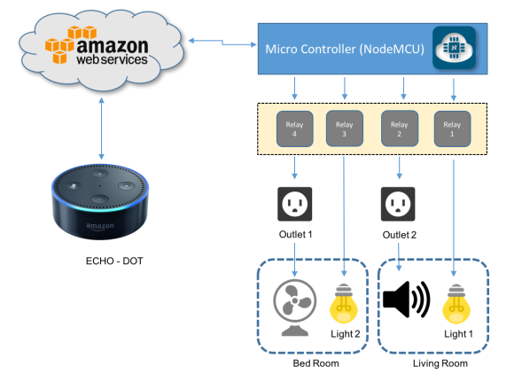
The below video, shows how the project will look like at end:

Step 1: Bill of Material (BoM)

All values are referencial in USD

  • LEDs (Red and Green) ($1.00)
  • 2 x Resistor (220 ohm)
  • External 5V power Supply or battery

Step 2: WeMo Emulation

 wemo_echo_upnp


The WeMo devices use UPnP to perform certain functions over the network. The device detection function starts out with the Echo or Dot (in our case here, the Dot) searching for WeMo devices using UPnP. The device then responds to the Dot with the device’s URL using HTTP over UDP. The Dot then requests the device’s description using that HTTP URL. The description is then returned as an HTTP response.The actual “on/off” functionality of the WeMo devices is simpler since the Dot already knows about the device. The Dot simply connects to the WeMo over the HTTP interface and issues a “SetBinaryState” command. The WeMo then obliges and returns a confirmation via HTTP. See the Echo/Dot Communication diagram above.

This tutorial will not go into much more detail on this topic. I sought to compile information from various web projects, simplifying their presentation to give an overview of Alexa’s use of home automation.

Some excellent sources of information about the subject can be found in the links below:

HOW TO MAKE AMAZON ECHO CONTROL FAKE WEMO DEVICES, wrote by Rick Osgut where you can learn the bases of WeMo emulation.

Building an IoT power switch with the ESP8266 (and control it with your Amazon Echo!) by Wai Lun

Amazon Alexa + WeMos switch made with Arduino D1 Mini by Aruna Tennakoon.

Projects using NodeMCU. by Christopher Kuzma

Saying that, from what I learned from the  sites, I finished with a test code that you can download from my GitHib : Alexa_LED_Control_V2_EXT.ino

Verify if you have all necessary libraries to run the code, like: ESP8266WiFi.h, ESP8266WebServer.h and WiFiUdp.h. You can get them here: Arduino core for ESP8266 WiFi chip.

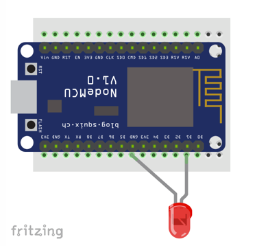
Step 3: Creating Our WeMo Device With NodeMCU

 Alex and NodeMCU

For our first test, let’s connect a LED at NodeMCU pin D1 as shown at above diagram.

Open the file Alexa_LED_Control_V2_EXT.ino that you downloaded from my GitHub and change the dummy wifi credentials, with your own:

const char* ssid = "YOUR SSID";
const char* password = "YOUR PASSWORD";

Confirm that you have properly defined the pin where the LED is connect and give a name for your device:

String device_name = "lights";  // Name of device
int relayPin = D1;              // Pin to toggle

In my case, the device will be named “Lights“. Here in this example is a single LED, but could be connected to a relay that will turn on the lights of my office.

Upload the code to your NodeMCU.

On Serial monitor you can see the message “Connecting to UDP” and “Connection Successful”. This means that from NodeMCU’s side it all OK.

Serial Monitor1

I assume that you already have Echo-Dot installed on your network, as well as the Alexa App on your smartphone. The procedures for installing both, are quite simple. Simply follow the Amazon instructions provided with the device.

Now, let’s ask to Alexa to find your device. There are 2 methods to do it:

  1. Using the Alexa App in your Smartphone as shown on the photos. In our case, Alexa will find “1 Smart Home device”: lights WeMo Switch.

Alexa app

Asking Alexa to do it directly using voice command, like: “Alexa, Find connected devices” as shown at the video below:

Once Alexa has discovery your device, you can give her voice commands as shown bellow:

Step 4: Working with Multiple Devices

IMG_1224

Let’s go deeper and develop a more realistic circuit with multiple devices that can be used with home automation.

We will use a 4 Channel relay module to control 2 lamps and 2 outlets.

This segment of the project was based on the great tutorial post by Charles Gantt, How To: DIY Home Automation With NodeMCU and Amazon Alexa.

Follow the below instructions:

Connect the Relays inputs with NodeMCU’s pins as bellow:

int relayOne = 14;  // NodeMCU pin D5
int relayTwo = 15;  // NodeMCU pin D8
int relayThree = 3; // NodeMCU pin RX
int relayFour = 1;  // NodeMCU pin TX

Our “smart devices” will be 2 fixed Lamps and 2 general Outlets. As you saw on the previous steps, we must emulate “WeMo Devices” and to do that we must name them as below:

  • Light One
  • Light Two
  • Outlet One
  • Outlet Two

Next we must define them in our code, so Alexa can understand it. We will also define 2 commands (on and off) and one Port number for each device.

The general format should be:

lightOne = new Switch("Light One", 80, lightOneOn, lightOneOff);
lightTwo = new Switch("Light Two", 81, lightTwoOn, lightTwoOff);
outletOne = new Switch("Outlet One", 82, outletOneOn, outletOneOff);
outletTwo = new Switch("Outlet Two", 83, outletTwoOn, outletTwoOff);

Now, you must define the 2 functions related with each device condition:

For Lights:

void lightOneOn() {
  Serial.print("Switch 1 turn on ...");
  digitalWrite(relayOne, LOW);   // sets relayOne on
}

void lightOneOff() {
  Serial.print("Switch 1 turn off ...");
  digitalWrite(relayOne, HIGH);   // sets relayOne off
}

void lightTwoOn() {
  Serial.print("Switch 2 turn on ...");
  digitalWrite(relayThree, LOW);   // sets relayTwo on
}

void lightTwoOff() {
  Serial.print("Switch 2 turn off ...");
  digitalWrite(relayThree, HIGH);   // sets relayTwo Off
}

And for Outlets:

void outletOneOn() {
  Serial.print("Socket 1 turn on ...");
  digitalWrite(relayFour, LOW);   // sets relayThree on
}

void outletOneOff() {
  Serial.print("Socket 1 turn off ...");
  digitalWrite(relayFour, HIGH);   // sets relayThree off
}

void outletTwoOn() {
  Serial.print("Socket 2 turn on ...");
  digitalWrite(relayTwo, LOW);   // sets relayFour on
}

void outletTwoOff() {
  Serial.print("Socket 2 turn off ...");
  digitalWrite(relayTwo, HIGH);   // sets relayFour off
}

In my case here I choose to test the 4 WeMo smart switches with devices powered with external 5 VDC. Once we have relays, we could have any type of real devices as TVs, refrigerators, etc.

  • As “Light 1”, we will use a Red LED
  • As “Light 2”, we will use a GREEN LED
  • As Outlet 2, we will use a small buzzer
  • As Outlet 1, we will use a small 5V fan

Follow the bellow electrical diagram to finish the HW connection.

Home Automation Electric Diagram

Download the complete code: NODEMCU_ALEXA_WeMos_4X_Serial_Monitor_EXT.ino from my GitHub.

Change the dummy wifi credentials, with your own:

const char* ssid = "YOUR SSID";
const char* password = "YOUR PASSWORD";

And that’s it!.

Follow the same procedure as defined on previous step to let Alexa find your 4 devices.

The video below shows a demo of this step:

Step 5: Home Automation

Now we have 4 smart devices working properly that can be individually turned on and off. But suppose that we want to group our devices to be used on our home. What should be done?

For example, suppose that our home has 2 rooms:

  • Bed Room
  • Living Room

Now, suppose that you want to have one lamp and one outlet in each room. So, let’s group our 4 devices as shown at the introduction block diagram:

  • IMG_9708Bed Room
    • Light 2
    • Outlet 1 (Fan)
  • Living Room
    • Light1
    • Outlet 2 (Buzzer)

We will also to create another group to deal with all devices at same time, turning on/off all device at same time.

So, let’s create a version 2 of our code were “3 new switches” should now be identified by Alexa, adding the following steps to our code:

  • Switch’s definition:
Switch *allDevices = NULL;
Switch *bedRoom = NULL;
Switch *livingRoom = NULL;
  • Group of devices on/off callbacks declaration:
void allDevicesOn();
void allDevicesOff();
void bedRoomOn();
void bedRoomOff();
void livingRoomOn();
void livingRoomOff();
  • Now, at setup(), let’s associate the switches with the new callbacks and Ports (remember that we have a maximum of 14 devices that can be handled with this code):
allDevices = new Switch("All Devices", 84, allDevicesOn, allDevicesOff);
bedRoom = new Switch("Bed Room", 85, bedRoomOn, bedRoomOff);
livingRoom = new Switch("Living Room", 86, livingRoomOn, livingRoomOff);
  • Adding Switches upnp Broadcast Responder at setup():
upnpBroadcastResponder.addDevice(*allDevices);
upnpBroadcastResponder.addDevice(*bedRoom);
upnpBroadcastResponder.addDevice(*livingRoom);
  • Append the lines to loop():
allDevices->serverLoop();
bedRoom->serverLoop();
livingRoom->serverLoop();
  • And finally, let’s create the proper group devices functions to react when Alexa receives a voice command:
void allDevicesOn() 
{
  Serial.print("All Devices turn on ...");
  digitalWrite(relayOne, LOW);   // sets relay1 on
  digitalWrite(relayTwo, LOW);   // sets relay2 on
  digitalWrite(relayThree, LOW);   // sets relay3 on
  digitalWrite(relayFour, LOW);   // sets relay4 on
}

void allDevicesOff() 
{
  Serial.print("All Devices turn off ...");
  digitalWrite(relayOne, HIGH);   // sets relay1 off
  digitalWrite(relayTwo, HIGH);   // sets relay2 off
  digitalWrite(relayThree, HIGH);   // sets relay3 off
  digitalWrite(relayFour, HIGH);   // sets relay4 off
}

void bedRoomOn() 
{
  Serial.print("Bed Room turn on ...");
  digitalWrite(relayThree, LOW);   // sets relay3 on
  digitalWrite(relayFour, LOW);   // sets relay4 on
}

void bedRoomOff() 
{
  Serial.print("Bed Room turn off ...");
  digitalWrite(relayThree, HIGH);   // sets relay3 off
  digitalWrite(relayFour, HIGH);   // sets relay4 off
}

void livingRoomOn() 
{
  Serial.print("Living Room turn on ...");
  digitalWrite(relayOne, LOW);   // sets relay1 on
  digitalWrite(relayTwo, LOW);   // sets relay2 on
}

void livingRoomOff() 
{
  Serial.print("Living Room turn off ...");
  digitalWrite(relayOne, HIGH);   // sets relay1 off
  digitalWrite(relayTwo, HIGH);   // sets relay2 off
}

The above procedure should be follow for any adicional device or group of devices that you want to add to your project.

You can download the complete code from my GitHub:

NODEMCU_ALEXA_WeMos_4X_V2_EXT

After the code is uploaded to NodeMCU, it is time to ask Alexa to “FIND DEVICES”. As explained before, you can do it using a voice command or the Alexa App. On both cases, the result can be verified at app as shown above. Seven devices (“WeMo Switches”) should be found now by Alexa:

  • IMG_1261Living Room
  • Bed Room
  • All Devices
  • Outlet One
  • Outlet Two
  • Light One
  • Light Two

The video below shows how our complete Home Automation project will work:

Step 6: Conclusion

 As always, I hope this project can help others find their way in the exciting world of electronics and IoT!

Please visit my GitHub for updated files:

Home-Automation-with-Alexa-and-NodeMCU

Saludos from the south of the world!

See you at my next tutorial!

Thank you

Marcelo

Continuemos nossa exploração pelo mundo do IoT, nas asas do NodeMCU! Neste tutorial, desenvolveremos uma estação meteorológica doméstica, onde se exibirá informações tais como temperatura e condições climáticas, tanto para o dia corrente quanto para os próximos 3 dias. Nossa estação também exibirá informações internas da casa, como temperatura e umidade relativa do ar.

O diagrama em blocos abaixo, nos dá uma visão geral sobre o projeto:

No vídeo abaixo, você pode ver como ficará o projeto final:

Continue lendo…