

EdgeAI made simple – Exploring Image Classification with Arduino Portenta, Edge Impulse, and OpenMV

Introduction
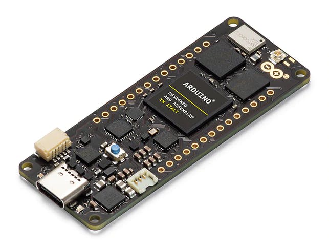
This tutorial explores the Arduino Portenta, a development board that includes two processors that can run tasks in parallel. Portenta can efficiently run processes created with TensorFlow™ Lite. For example, one of the cores computing a computer vision algorithm on the fly (inference), having the other leading with low-level operations like controlling a motor and communicating or acting as a user interface.
The onboard wireless module allows the management of WiFi and Bluetooth® connectivity simultaneously.
Two Parallel Cores
H7’s central processor is the dual-core STM32H747, including a Cortex® M7 running at 480 MHz and a Cortex® M4 running at 240 MHz. The two cores communicate via a Remote Procedure Call mechanism that seamlessly allows calling functions on the other processor. Both processors share all the on-chip peripherals and can run:
- Arduino sketches on top of the Arm® Mbed™ OS
- Native Mbed™ applications
- MicroPython / JavaScript via an interpreter
- TensorFlow™ Lite
Memory
Memory is crucial for embedded machine Learning projects. Portenta H7 board can host up to 64 MB of SDRAM and 128 MB of QSPI Flash. In my case, my board comes with 8MB of SDRAM and 16MB of Flash QSPI. But it is essential to consider that the MCU SRAM is the one to be used with machine learning inferences; that for the STM32H747 is only 1MB. This MCU also has incorporated 2MB of FLASH, mainly for code storage.
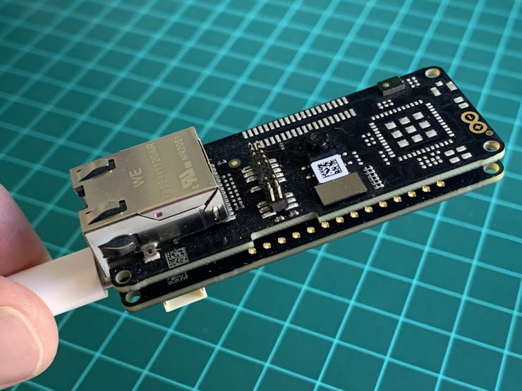
Vision Shield
We will add a Vision Shield to our Portenta board for use in vision applications, which brings industry-rated features, like Ethernet (or LoRa), camera, and microphones.
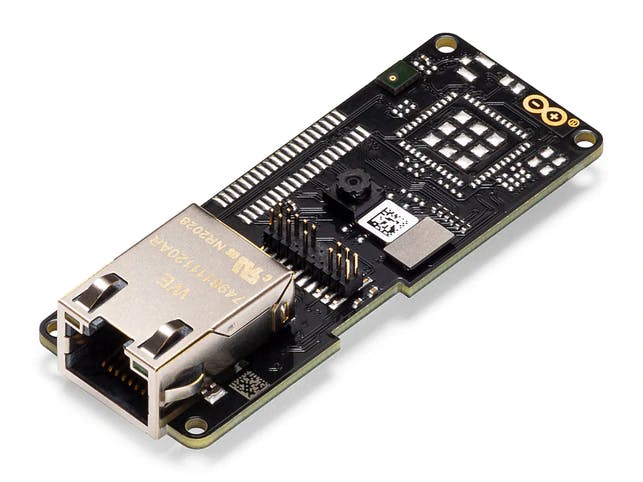
- Camera: Ultra-low-power Himax HM-01B0 monochrome camera module with 320 x 320 active pixel resolution support for QVGA.
- Microphone: 2 x MP34DT05, an ultra-compact, low-power, omnidirectional, digital MEMS microphone built with a capacitive sensing element and an IC interface.
Installation and tests
Start connecting the board (USB-C) to your computer :
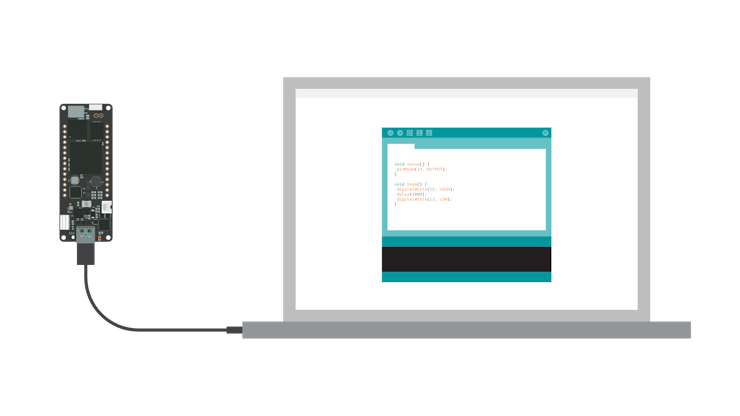
Install the Mbed OS core for Portenta boards in the Arduino IDE.
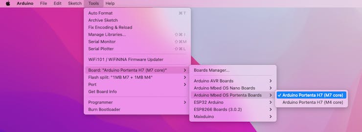
Having the IDE open, navigate to Tools > Board > Board Manager and look for portenta on the search window:
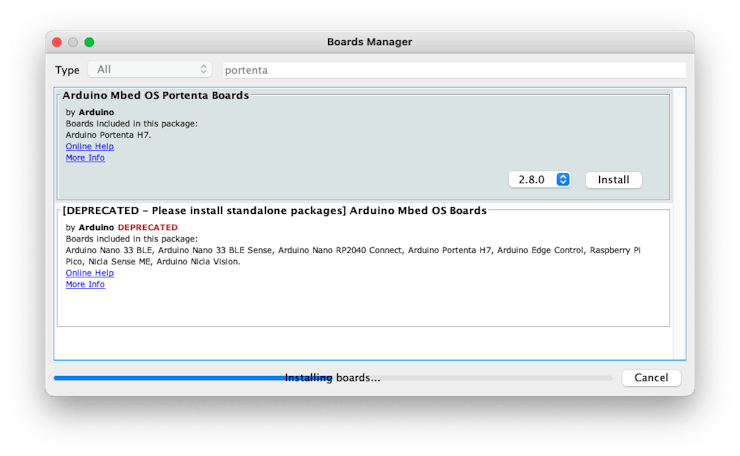
Next, go to Tools > Board > Arduino Mbed OS Portenta Boards and select Arduino Portenta H7
Having your board connected to the USB, you should see the Portenta on Port.
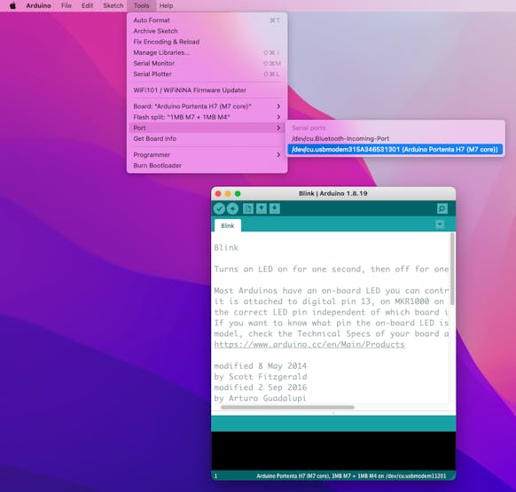
Open the Blink sketch on Examples/Basic and run it using the IDE Upload button. You should see the Built-in LED (green) blinking.
The Portenta H7 board is correctly installed and functional!
Testing the Microphones
Having the Visual Shield connected, let’s start testing the Mics:
On Arduino IDE go to Examples > PDM > PDM > SerialPlotter and open the sketch. It would help if you changed some parameters to use the PDM.h library:
// default number of output channels
static const char channels = 2;

// default PCM output frequency
static const int frequency = 32000;

// Buffer to read samples into, each sample is 16-bits
short sampleBuffer[512];
Open the Plotter and see the audio representation from both microphones (Left and right):
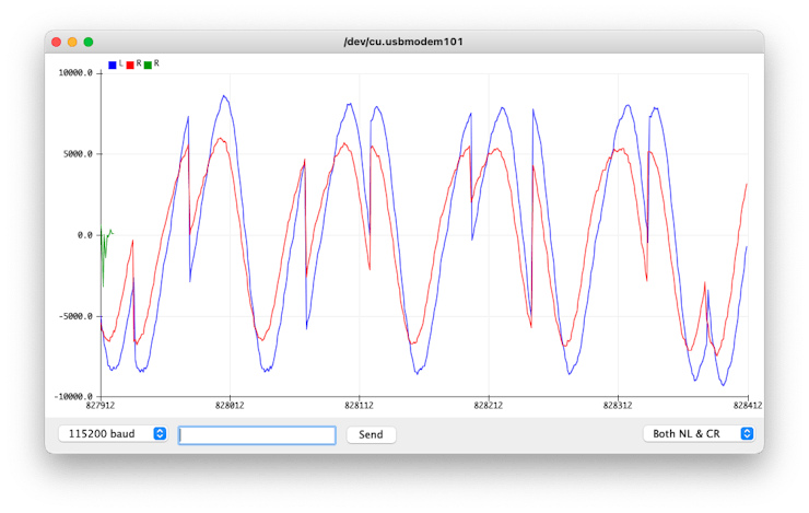
Vary the frequency of the sound that you are generating and confirm that the mics are working correctly:

Testing the Camera
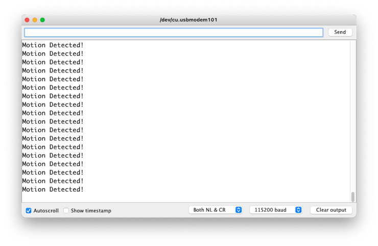
We can also test the camera, using, for example, the code provides on Examples > Camera > CamaraMotionDetect. Of course, you can not see the image, but it is possible to prove at least that the camera senses changes in the light.
Uploading this sketch to Portenta, you can see the Blue RGB LED flashing whenever you move something in front of the camera. Also, you can see “Motion Detected!” appearing in the Serial Monitor.
We could also capture and see the raw data, but the best test with the camera is to see an image. For that, we will use another IDE, the OpenMV.
Installing the OpenMV IDE
OpenMV IDE is the premier integrated development environment for use with OpenMV Cameras and the one on the Portenta. It features a powerful text editor, debug terminal, and frame buffer viewer w/ a histogram display. We will use MicroPython to program the camera.
Go to the OpenMV IDE page, download the correct version for your Operating System and follow the instructions for its installation on your computer.
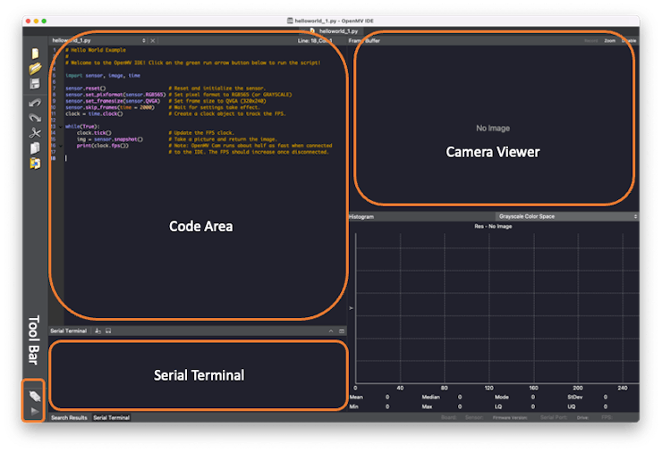
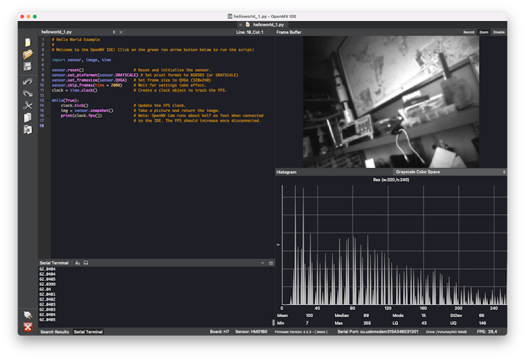
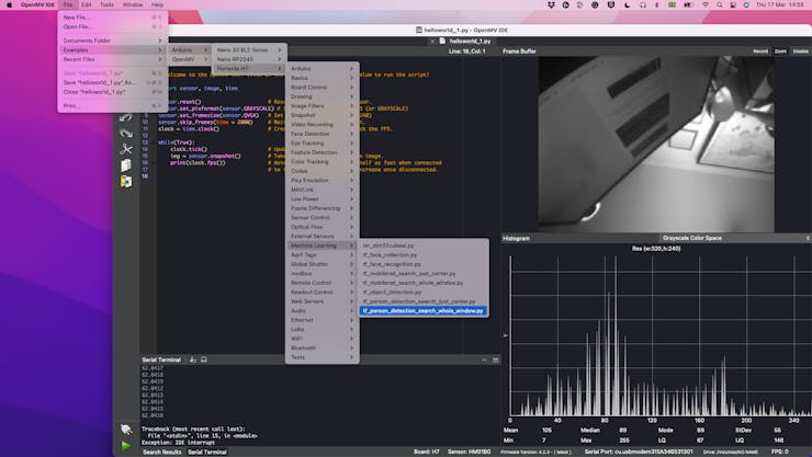
The IDE should open, showing by default the helloworld_1.py code on its Code Area. During run time, any messages sent thru serial connection (using print() or error messages) will be displayed on the Serial Terminal. Once we have the Portenta+Vision_Shield connected, the image captured by its camera will be displayed on the Camera ViewerArea (or Frame Buffer) and at the Histogram area, immediately below the Camera Viewer.
Note that you can select among several Color Spaces. We should choose the Grayscale to work with the Portenta camera.
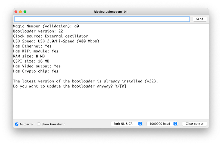
Before you connect the Portenta to OpenMV, make sure that you have the latest version of the bootloader. To that, go to your Arduino IDE and open the sketch on: Examples > STM_32H747_System > STM_32H747_updateBootloader
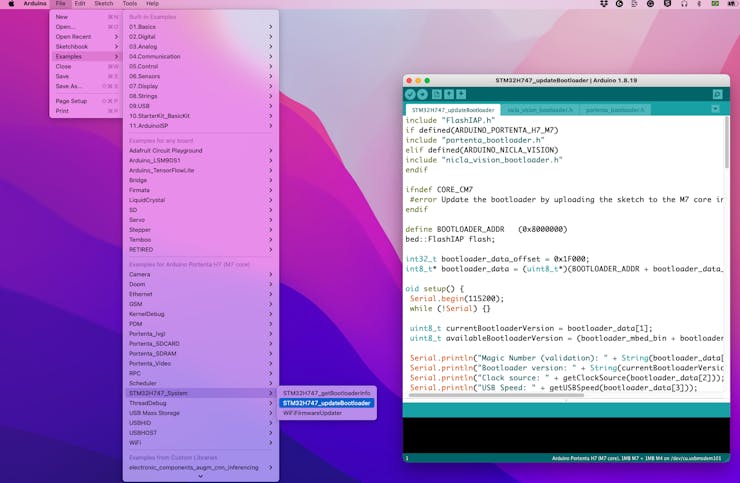
Upload the code to your board. The Serial Monitor will guide you.
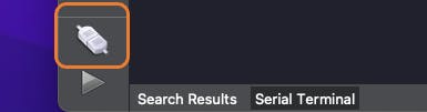
After updating the bootloader, put the Portenta in bootloader mode by double-pressing the reset button on the board. The built-in green LED will start fading in and out. Now return the OpenMV IDE and click on connect icon (Left ToolBar):
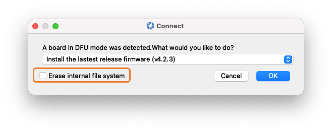
A pop-up will tell you that a board in DFU mode was detected and ask you how you would like to proceed. First, select “Install the latest release firmware.” This action will install the latest OpenMV firmware on the Portenta H7. You can leave the option of erasing the internal file system unselected and click “OK.”
Portenta H7’s green LED will start flashing while the OpenMV firmware is uploaded to the board. Then, a terminal window will open, which shows you the flashing progress.
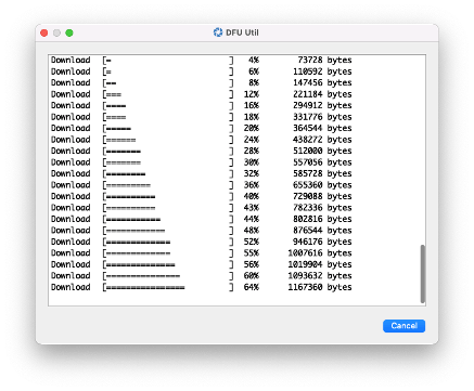
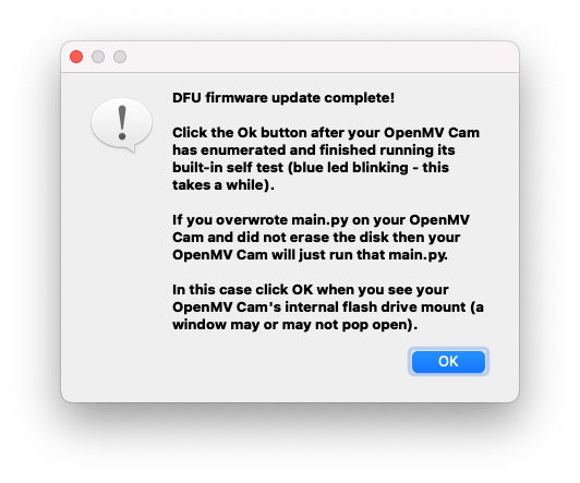
Wait until the green LED stops flashing and fading. When the process ends, you will see a message saying, “DFU firmware update complete!”.
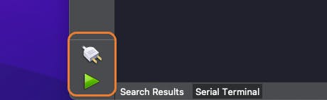
A green play button appears when the Portenta H7 is successfully connected at the Tool Bar.
When clicking the green play button, the Micropython script (hellowolrd.py) on the Code Area will be uploaded and run on the Portenta. On-Camera Viewer, you will start to see the video streaming. The Serial Monitor will show us the FPS (Frames per second), which should be over 60fps, which is awesome!
Let’s go through the helloworld.py script:
import sensor, image, time

sensor.reset()                         # Reset and initialize the sensor.
sensor.set_pixformat(sensor.GRAYSCALE) # Set pixel format to RGB565
                                       # (or GRAYSCALE)
sensor.set_framesize(sensor.QVGA)      # Set frame size to QVGA (320x240)
sensor.skip_frames(time = 2000)        # Wait for settings take effect.
clock = time.clock()                   # Create a clock object to track the
                                       # FPS.

while(True):
    clock.tick()                    # Update the FPS clock.
    img = sensor.snapshot()         # Take a picture and return the image.
    print(clock.fps())              # Note: OpenMV Cam runs about half as fast
                                    # when connected to the IDE. The FPS
                                    # should increase once disconnected.
The code can be split into two parts:
- Setup: Where the libraries are imported and initialized and the variables.
- Loop: part of the code that runs continually. Here the img variable is captured (a frame). Each of those frames can be used for inference in Machine Learning Applications.
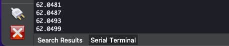
For interrupting the program execution, press the red [X] button.
Person Detection using TensorFlow
Now that we tested our camera and the OpenMV IDE adequately installed and running our Portenta board, let’s try the MicroPython TensorFlow framework, with a classical deep learning example, the Visual Person Detection.
On the OpenMV menu, go to Examples > Arduino > Portenta H7 > Machine Learning and open the script tf_person_detection_search_whole_window.py
Now, let’s comment on the essential parts of the code:
Initialization setup:
import sensor, image, time, os, tf

sensor.reset()                         # Reset and initialize the sensor.
sensor.set_pixformat(sensor.GRAYSCALE) # Set pixel format to RGB565 (or GRAYSCALE)
sensor.set_framesize(sensor.QVGA)      # Set frame size to QVGA (320x240)
sensor.set_windowing((240, 240))       # Set 240x240 window.
sensor.skip_frames(time=2000)          # Let the camera adjust.
Note that the library tf (TensorFlow) is also imported. The tf module is capable of executing Quantized TensorFlow Lite Models. During the initialization, besides setting up the camera frame size to QVGA, we also need to define the image window size used for inference. The 240 x 240 is selected because the ML model used this shape as an input tensor. Now, let’s load the built-in person detection model (net) and its labels:
labels, net = tf.load_builtin_model('person_detection')
labels is a list:
['no_person', 'person']
Where:
labels[0]= 'no_person'
labels[1] = 'person']
The last initialization instruction is to create the object clock for use with FPS tracking
clock = time.clock()
While Loop:
We will start the while loop updating the FPS clock and capturing a frame:
clock.tick()
img = sensor.snapshot()
The img will be used as the input of the model.
In our case, net.classify() will run the network on the whole image, but it always generates a list of results. So, once we handle only one window, obj has only one component. In the full code, for simplicity, we will use:
obj = net.classify(img)[0]
Below is an example of obj[0] generated by net.classify:
{"x":0, "y":0, "w":240, "h":240, "output":[0.257813, 0.742188]}
the above result, means that a classification score output vector as “output”:[0.257813, 0.742188] was generated for the whole window “x”:0, “y”:0, “w”:240, “h”:240. This output means that the index 0 (‘no_person’) scores 0.26 and the index 1 (‘person’) scores 0.74, which means that the image (img) should be a person.
The machine learning magic is done! Now it is only post-processing work, as writing the labels and its scores on Serial Terminal:
for i in range(len(obj.output())):
    print("%s = %f" % (labels[i], obj.output()[i]))

print(clock.fps(), "fps")
and write the label with the highest score at the left-up border of the image:
img.draw_string(
    obj.x()+3,
    obj.y()-1,
    labels[obj.output().index(max(obj.output()))],
    mono_space = False
    )
here
Here is the complete simplified code (you can “copy/paste” it to OpenMV IDE:
import sensor, image, time, os, tf

sensor.reset()                         # Reset and initialize the sensor.
sensor.set_pixformat(sensor.GRAYSCALE) # Set pixel format to GRAYSCALE
sensor.set_framesize(sensor.QVGA)      # Set frame size to QVGA (320x240)
sensor.set_windowing((240, 240))       # Set 240x240 window.
sensor.skip_frames(time=2000)          # Let the camera adjust.

# Load the built-in person detection network.
labels, net = tf.load_builtin_model('person_detection')

clock = time.clock()
while(True):
    clock.tick()
    img = sensor.snapshot()             # capture the input image

    obj = net.classify(img)[0]          # Do the inference

    print("**********\nDetections at [x=%d,y=%d,w=%d,h=%d]"
        % obj.rect())
    for i in range(len(obj.output())):
        print("%s = %f" % (labels[i], obj.output()[i]))
    img.draw_string(
        obj.x()+3,
        obj.y()-1,
        labels[obj.output().index(max(obj.output()))],
        mono_space = False
        )
    print(clock.fps(), "fps")
Below we can see the result:
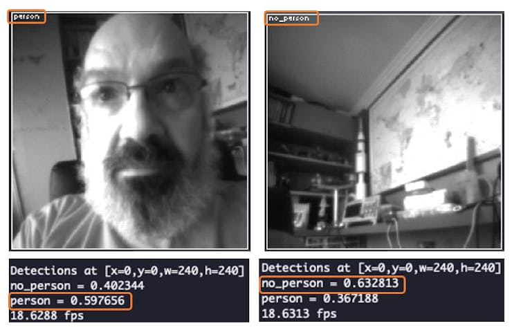
Note that the inference is happening around 18 times per second, what is very good for real time applications. And runing stand alone, discinecte from the OpenMV IDE, the FPS is even higher.
Image Classification Project
Now that we are sure that our Portenta is working correctly and capable of running machine learning models relatively fast, let’s work on a project from scratch.
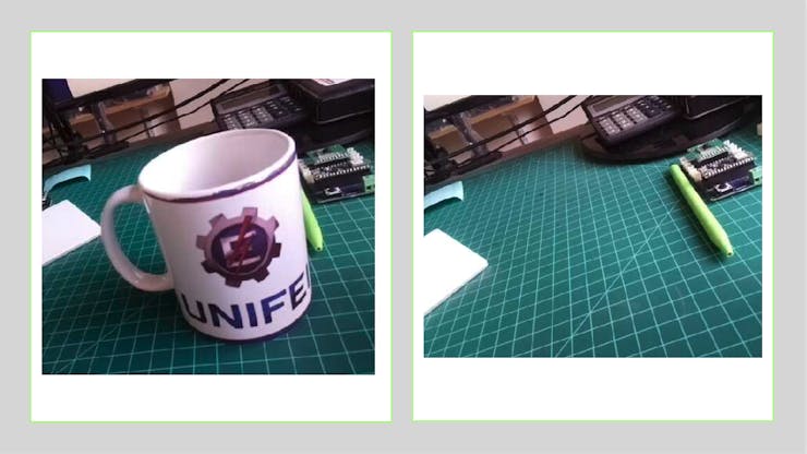
Our Goal
Detect if one specific object is present in our image. In our case, the mug from my university:
Every Machine Learning project starts with dataset collection. You can use the OpenMV IDE that we just installed or even your phone. But once our ultimate goal is to train our model on Edge Impulse Studio, we will start from there!
Connecting Portenta with Edge Impulse Studio
Go to Edge Impulse Studio, enter with your credentials at Login (or create an account), and start a new project.

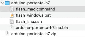
Next, go to Arduino Portenta H7 + Vision shield and download the latest Edge Impulse firmware. A.ZIP file will be downloaded to your computer. It contains three files. Choose the correct one for your Operating System.
- Double press the RESET button on your board to put it in the bootloader mode.
- Open the flash script for your operating system. In my case: flash_mac.command, to flash the firmware.
- Wait until flashing is complete, and press the RESET button once to launch the new firmware.

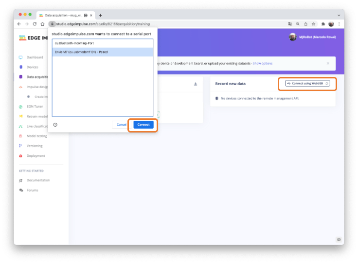
Go to your project page (Data Acquisition section) at EI Studio, and using webUSB, connect your Portenta:
Dataset Collection
Now you should define the label of your sample (in our case, mug or no_mug) and select your sensor (microphone or camera). In our case: Camera (320×320).
Start collecting your samples for both classes. At least around 50 samples for “mug”
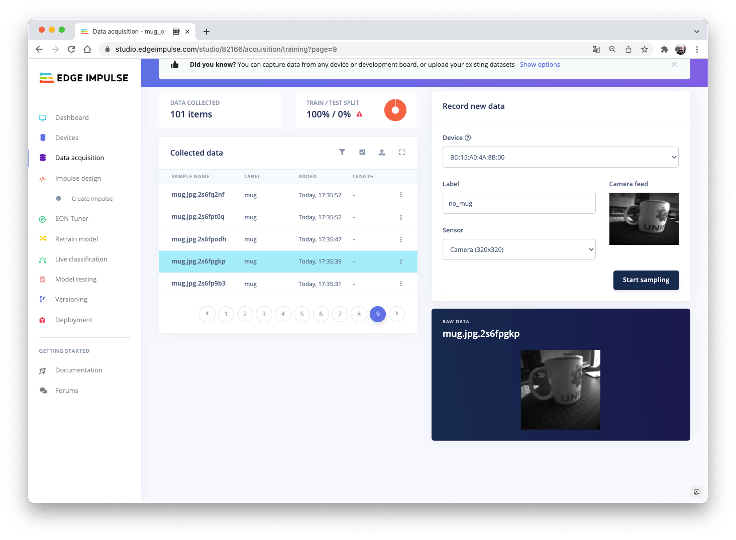
And another 50 samples for “no_mug”

Now, split your data in Train/test. For example, sparing 20 of your samples for test after train (10 for each class). You can do it manually sample by sample using the option “Move to test set” on the three dots menu found on each sample. Another option is to leave it to the Studio to split it. Go to the bottom of the Dashboard section and use “Perform train/test split.”
Create Impulse and Generate features
An impulse takes raw data in the 320×320 pixels images, cropping them for 96×96 for optimal accuracy with the Transfer Learning Model.
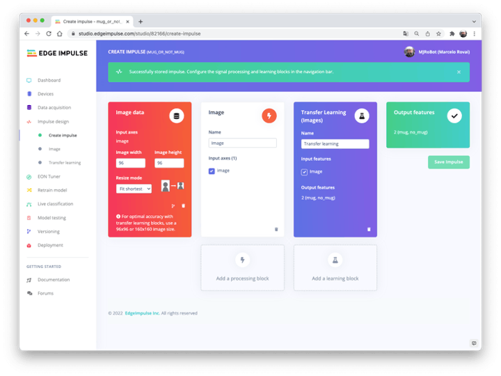
The cropping is the only preprocessing that our input images will suffer once the images are already in grayscale.
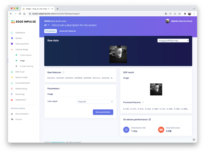
Save the parameters and generate the features. Then, take a look at the feature explorer:

As expected, applying UMAP for reducing dimensions, we can confirm that samples are visually easily classified, which is an excellent sign that the model should work well.
Training and Test
For training, we should select a pre-trained model. Let’s use the MobileNetV2 96×96 0.35. This model uses around 300K RAM and 575K of ROM (Flash), which suits well with our board once it has 1MB of RAM and 2MB of ROM.
Regarding the training hyper-parameters, the final hidden layer (before Flatten layer) will have 16 neurons, and a dropout normalization of 10% (0.1) will be used to prevent overfitting. At first pass, the model will be trained with 20 epochs and a learning rate of 0.0005.
For validation during training, will be spared 20% from the dataset (validation_dataset). For the remaining 80% (train_dataset), we will apply Data Augmentation, which randomly will flip, change the size and brightness of the image, and crop them. We artificially increase the number of samples on the dataset for training.
As a result, the model ends with practically 100% of accuracy.
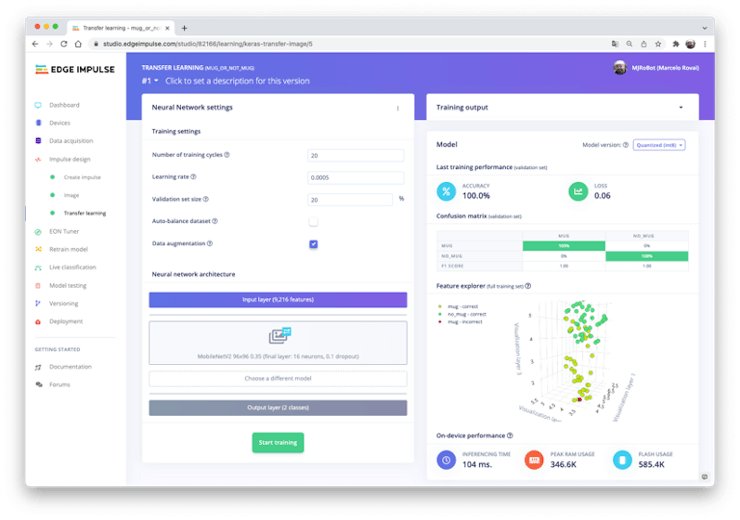
The same result was reached with the model test.
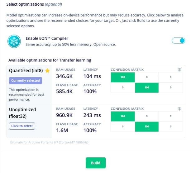
Deployment
We will deploy the model in two ways:
- Arduino Library (C/C++) to be tested with Arduino IDE
- OpenMV (.lite model) to use with the OpenMV (MicroPython).
Arduino Library
The Arduino library will be built and downloaded as a.zip file to your computer. Open the Arduino IDE and go to Sketch > Include Library > add.ZIP Library…
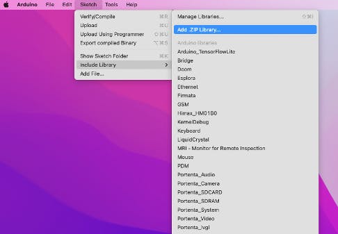
And select the file downloaded from Edge Impulse.
Go to Arduino IDE Examples > mug_or_not_mug_inference > portenta_h7_camera
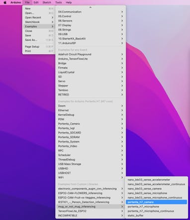
Upload the sketch:
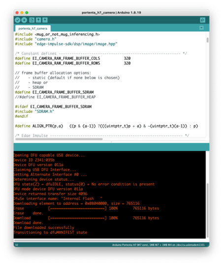
and open the Serial Monitor. You can start classifying your images looking for Mugs!
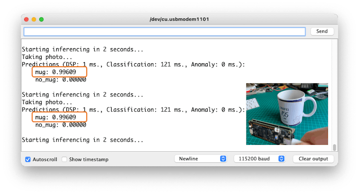
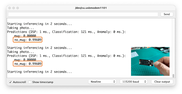
It is working! It is straightforward to develop a Machine Learning project with Edge Impulse! But having the power of Arduino Portenta in our hands, let’s also deploy the model and perform the inference using MicroPython!
OpenMV
1. Go to the Edge Impulse Dashboard section,
2. Download the Int8 Quantized Transfer Learning Model
3. Get the model on your computer Download Folder
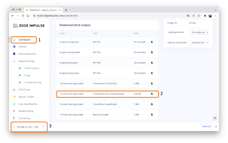
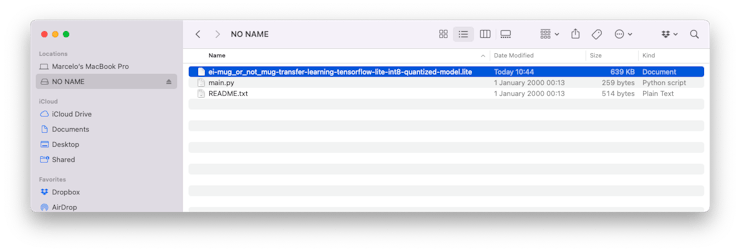
ei-mug_or_not_mug-transfer-learning-tensorflow-lite-int8-quantized-model.lite
Having your Portenta connected to the OpenMV IDE, you should see a “NO NAME” drive on your File Manager. Move (or copy) the downloaded.lite model into this drive:
Now, let’s create a MicroPython code on OpenMV IDE:
import the libraries:
import sensor, image, time, tf
Define the model location. We will keep it on the Portenta root file directory:
model_file = "ei-mug_or_not_mug-transfer-learning-tensorflow-lite-int8-quantized-model.lite"
Define a labels list. Edge Impulse Studio usually keeps the labels in alphabetic order :
labels = ["mug", "no_mug"]
Now configure the camera. Remember that Portenta’s Vision Shield captures images only as Grayscale. Also, let’s define the window for image capture the same as the model’s input tensor:
sensor.reset()
sensor.set_pixformat(sensor.GRAYSCALE)  # Set pixel format
sensor.set_framesize(sensor.QVGA)       # Set frame size to QVGA
sensor.set_windowing((96, 96))          # Crop to model resolution
sensor.skip_frames(time = 2000)         # Let the camera adjust
Start clock (for measuring FPS)
clock = time.clock()
Now, let’s code the main while loop. Start updating timer:
clock.tick()
Get an image from the camera. In my case, I will also mirror the image:
img = sensor.snapshot()
img.set(h_mirror=True)
Using tf.classify(), do the inference that executes the TensorFlow Lite image classification model on the img object and returns a list of tf_classification objects. We should only get one item in the predictions list, so we extract the output probabilities from that.
objs = tf.classify(model_file, img)
predictions = objs[0].output()
Note that predictions is a list with two elements, with the probabilities of each class. For example, take the below predictions for a given frame:
predictions = [0.0820313, 0.917969]
From the above example, predictions[0] shows that a specific frame has around 8% of probability of having a mug on it and 92% of no have (predictions[1]).
Now, let’s find the label with the highest probability
max_val = max(predictions)
max_idx = predictions.index(max_val)
and draw a label with the highest probability to the image viewer
img.draw_string(
    0, 0,
    labels[max_idx] + "\n{:.2f}".format(round(max_val, 2)),
    mono_space = False,
    scale=1
    )
To finish, we will print on Serial Terminal, the probabilities for both classes and also the FPS (Frames per Second)
print("-----")
for i, label in enumerate(labels):
    print(str(label) + ": " + str(predictions[i]))
print("FPS:", clock.fps())
Save the complete below script as main.py on NO_NAME drive (the Portenta).
import sensor, image, time, tf

# Location of TFLite model file and Labels list
model_file = "ei-mug_or_not_mug-transfer-learning-tensorflow-lite-int8-quantized-model.lite"
labels = ["mug", "no_mug"]

# Configure camera
sensor.reset()
sensor.set_pixformat(sensor.GRAYSCALE)  # Set pixel format to GRAYSCALE
sensor.set_framesize(sensor.QVGA)       # Set frame size to QVGA (320x240)
sensor.set_windowing((96, 96))          # Crop to model resolution
sensor.skip_frames(time = 2000)         # Let the camera adjust

# Start clock (for measureing FPS)
clock = time.clock()

# Main while loop
while(True):

    # Update timer
    clock.tick()

    # Get image from camera
    img = sensor.snapshot()
    img.set(h_mirror=True)

    # Do inference and get predictions
    objs = tf.classify(model_file, img)
    predictions = objs[0].output()

    # Find label with the highest probability
    max_val = max(predictions)
    max_idx = predictions.index(max_val)

    # Draw label with highest probability to image viewer
    img.draw_string(
        0, 0,
        labels[max_idx] + "\n{:.2f}".format(round(max_val, 2)),
        mono_space = False,
        scale=1
        )

    #Print all the probabilities
    print("-----")
    for i, label in enumerate(labels):
        print(str(label) + ": " + str(predictions[i]))
    print("FPS:", clock.fps())
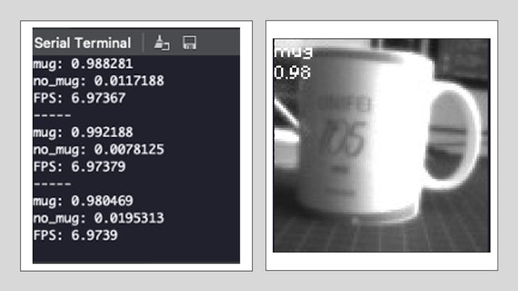
Run the script using the Green Play button in the OpenMV IDE. Here is the result:
Making off-line (or stand-alone) inference
Of course, the great advantage of tinyML applications is to run inference on fully stand-alone devices. So, you only need the OpenMV IDE for code development. But, in the real world, you will not have a serial Terminal or Image Viewer to tell you the output classification of your model.
So, let’s modify our code to add some LEDs to tell us what the Portenta is classifying:
- LED GREEN = MUG
- LED RED = N0 MUG
For that, we will import a new library pyb, initializing the LEDs
import pyb
ledRed = pyb.LED(1)   # Initiates the red led
ledGreen = pyb.LED(2) # Initiates the green led
And inside the loop, once we have calculated the variable max_idx, which indicates the class with the highest score, we can write the below code:
if max_idx == 0:    # turn on red led
    ledRed.off()
    ledGreen.on()
else:               # turn on green led
    ledRed.on()
    ledGreen.off()
Here is the result:
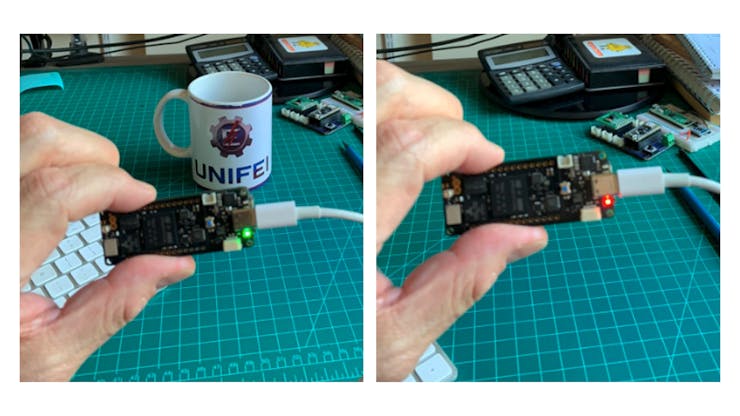
Note that if you have the Portenta disconnected from the OpenMV IDE and operated with an external battery, for example, once you press reset, the main.py script that are stored inside the Portenta (root) will be automatically executed.
Conclusion
The Arduino Portenta is a very flexible and easy to program device. This project showed the potential of TinyML, and its overall results applied it to real applications. The model used for transfer learning is not tiny and worked properly (MobileNet V2 with α=0.35), showing that Portenta is suitable for Visual applications. Furthermore, its camera uses very little power, which means that we can use it continuously. With both deployments (C/C++ and MicroPython), the model inference took respectively 120ms (Arduino IDE) and 140ms (OpenMV IDE).
Of course, the inference time should be even lower without serial communication with the IDEs (Edge Impulse Studio predicts around 104ms).
My next project with the Portenta will explore sensor fusion (camera + microphone) and object detection.
I hope this project can help others find their way in the exciting world of AI and Electronics!
link: MJRoBot.org
Greetings from the south of the world!
See you at my next project!
Thank you
Marcelo


