
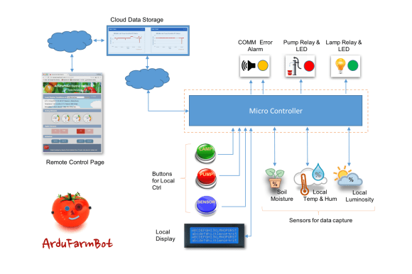
 The general idea behind ArduFarmBot, is to capture information from a tomato plantation, as temperature, relative air humidity, luminosity and soil humidity and based on those data decide the right amount (and when) the plantation should receive heat and water. Also the project should allow manual intervention of an operator in order to control a water pump and an electric lamp to generate heat for the plantation. The manual intervention must be both, local and remote via Internet.
In short, the system should receive as input:
- Sensors (analog data):
- Temperature
- Humidity
- Luminosity
- Soil Moisture
- Buttons:
- Pump ON/OFF
- Lamp ON/OFF
The system should provide as an output:
- Actuators:
- Relay for Pump control
- Relay for Lamp control
- Signalization (digital data):
- Visual and sound for status/error indication
- Visual for Pump status
- Visual for Lamp status
- Data Display
- All analog and digital data should be available for instant evaluation
- Data Storage
- Historic data should be storage remotely and optionally also locally.
The bellow block diagram shows the main components of the project.
The video bellow describe the first laboratory prototype used for testing:
And this one shows how the commands will work local and remotely via WebPage:
The project will be divided in 3 parts:
- Local Station
- Remote Station (IoT)
- Application and Follow up at farm
Here in this first part, we will explore the Local Station, taking care of sensors, actuators, learning how to display data, etc. In the ArduFarmBot – Part 2: “Remote Station” an IoT Implementation, as the name explains, we will we will implement an IoT approach were this “manual intervention” will be also possible remotely via Internet.
PART 1 – LOCAL STATION

1.1: Bill of Material
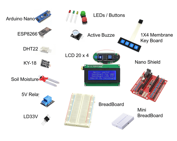
General items (around $37.00):
- Arduino Nano – ($7.50)
- Temperature and Humidity Sensor DHT22 – ($3.66)
- Luminosity Sensor – AD-018 Photo resistor module. or any equivalent – ($0.71)
- Soil Moisture Sensor – ($1.99) (Optional, can be DIY)
- LCD I2C 20X4 ($13.99)
- Buttons (2X) – ($0.90)
- LEDs (3X) ($0.20)
- Esp8266 Serial Wifi Wireless Transceiver Module Esp-01 – ($5.96) – (To be used on Part 2)
- Active Buzzer – Ky-12 or equivalent ($0.60) – (To be used on Part 2)
- 2 X 5v Relay Module ($11.60)
- Jump wires (S1.00)
- 10KOhms resistor – ($0.03)
- 2.2K Ohms resistor – ($0.03)
- 1.0K Ohms resistor – ($0.03)
- 220 Ohms resistor – ($0.03)
Option 1 with Nano Shield (around $15.00):
- Arduino Nano Shield (“Funduino”) – ($7.28)
- Membrane keyboard (4 Keys) – ($6.65)
- Breadboard Mini ($1.00) (To be used on Part 2)
Option 2 w/o Nano-Shield (around $4.00):
- 3.3V Voltage Regulator LD33V or equivalent ($1.20) (To be used on Part 2)
- Capacitor – Electrolytic 10uF (2X) to be used with 7803 – ($0.10)
- BreadBoard medium – ($2.50)
For laboratory tests, a Breadboard Power Supply Module 3.3V/5V ($5.99) can also be used for the ESP8266. (To be used on Part 2)
1.2: Installing, programing and testing the sensors

DHT 22 (or DHT11)
The first sensor to be installed and tested is the DHT 22, a digital relative humidity and temperature sensor. It uses a capacitive humidity sensor and a thermistor to measure the surrounding air, and spits out a digital signal on the data pin (no analog input pins needed).
According its Datasheet , the sensor should be powered between 3.3V and 5V (some datasheets say 6V max) and will work from -40oC to +80oC ( some datasheets say +125oC) with an accuracy of +/- 0.5oC for temperature and +/-2% for relative Humidity. It is also important to have in mind that the its sensing period is in average 2seconds (minimum time between readings).
The site of Adafruit provides a lot of information about both, DHT22 and its brother DHT11. For more details, please visit: DHT22/11 Tutorial page .
The DHT22 has 4 pins (facing the sensor, pin 1 is the most left) :
- VCC (3 to 5V power)
- Data out
- Not connected
- Ground
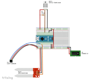
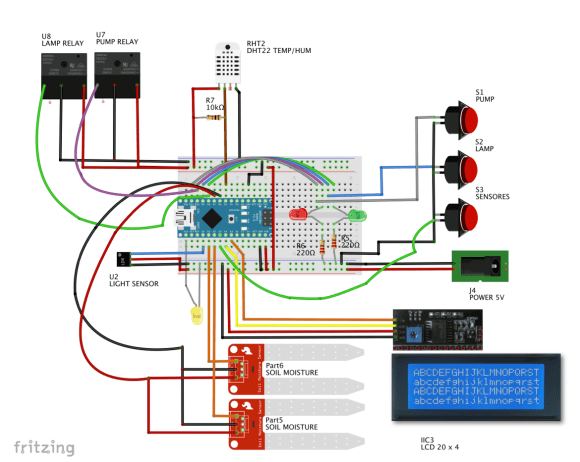
Once usually you will use the sensor on distances less than 20m, a 10K resistor should be connected between Data and VCC pins. The Output pin should be connected to Arduino pin 5 (see the diagram above).
Once the sensor is installed at Arduino, download the DHT library from Adafruit github repository and install it in your Arduino’s Library file.
Once you reload your Arduino IDE, the “DHT sensor library” should be installed. Run the DHT Sensor code to verify that everything is running OK:
/****************************************************************
 * DHT Sensor - Setup and Test
 * Based on the original code written by ladyada, public domain
 * MJRoBot 21Aug16
 ****************************************************************/
// Include DHT Library
#include <DHT.h>

// Sensor defiitions
#define DHTPIN 5        // DHT data pin connected to Arduino pin 5
#define DHTTYPE DHT22   // DHT 22 (if your sensor is the DHT 11, only change this line by: #define DHTTYPE DHT11)

// Variables to be used by Sensor
float tempDHT; // on the final program we will use int insteady of float. No need for high precision measurements
float humDHT;
float hic; // only used here for testing purposes

// Initialize the DHT sensor
DHT dht(DHTPIN, DHTTYPE);

void setup()
{
  Serial.begin(9600);
  Serial.println("DHT 22 Setup & Test");
  dht.begin();
}

void loop()
{
  // Wait a few seconds between measurements.
  delay(2000);

  //Read temperature and humidity values from DHT sensor:
  tempDHT = dht.readTemperature();
  humDHT = dht.readHumidity();

  // Check if any reads failed and exit early (to try again).
  if (isnan(humDHT) || isnan(tempDHT))
  {
    Serial.println("Failed to read from DHT sensor!");
    return;
  }

  // Compute heat index in Celsius (isFahreheit = false)
  float hic = dht.computeHeatIndex(tempDHT, humDHT, false);

  // Show measurements at Serial monitor:
  Serial.print("   Temp DHT ==> ");
  Serial.print(tempDHT);
  Serial.print("oC  Hum DHT ==> ");
  Serial.print(humDHT);
  Serial.print("%  Heat index: ");
  Serial.print(hic);
  Serial.println(" oC ");
}
Luminosity Sensor
Once the DHT is installed and tested, it’s time for the luminosity sensor. For that, a simple LDR (Light Dependent Resistor) can be used. Basically what we should to do is to have a Voltage Divider, where one of the resistors is the LDR and the middle point of the divider should be used as an analog input for Arduino. This way, varying the light, the LDR resistance varies and so, the middle point voltage of the divider will also change proportionally.
For test here, we will use a cheap LDR module (KY18) that has the voltage divider integrated. The module has 3 pins (“S” for data; “+”for VCC and “-” for GND). The pin “S” will be connected connected to Arduino Pin Analog 0. The “+” and “-” pins should be connected respectively to 5V and GND. If Power consumption is a concern, the “+” could be connected to one of the Arduino’s digital output instead, that should be “HIGH” a few milliseconds before you read the voltage at pin A0, returning to “LOW” after that.
The function getLumen(LDR_PIN); read a few times the sensor output (could be 3, 10 or more, you decide what it is best for your case) calculating the average of those readings. Also, once the output of the output of Arduino Analog Digital converter (ADC) is a number from 0 to 1023, we should “Map” those values in order to get the following results:
- “Full Dark”: ADC output: 1023 ==> 0%
- “Full Light”: ADC output: 0 ==> 100%
int getLumen(int anaPin)
{
  int anaValue = 0;
  for(int i = 0; i < 10; i++) // read sensor 10X ang get the average
  {
    anaValue += analogRead(anaPin);
    delay(50);
  }

  anaValue = anaValue/10; //Light under 300; Dark over 800
  anaValue = map(anaValue, 1023, 0, 0, 100); //LDRDark:0  ==> light 100%

  return anaValue;
}
Soil Moisture Sensor
A sensor for testing soil moisture is very simple. It has the same principle as the Luminosity sensor. A voltage divider to be used as input of one of Arduino’s Analog Pin, but instead of a “Light Depending Resistor”, we will have a “Soil Humidity Depending resistor”. The basic circuit is really simple and can be seen above.
 Unfortunately, the reality is a little bit more complex than this (but not much). The simple sensor as described before would work fine, but not for long. The problem is that having a constant current flowing thru the electrodes in one single direction will generate corrosion on them due the electrolysis effect. One way to solve it is to connect the electrodes not at VCC and Ground, but to Arduino Digital ports. Doing that, first the sensor would be “energized” only when the reading should really happen and the current direction over the probes could be done on both directions, eliminating the electrolysis’s effect.
Bellow simple test code was based on the post “How to: Soil Moisture Measurement?” :
/****************************************************
Soil Moisture Sensor Test
****************************************************/
#define SOIL_MOIST_PIN 1 // used for Soil Moisture Sensor Input
#define SMS_VCC 7
#define SMS_GND 6

int soilMoist; // analogical value obtained from sensor

void setup ()
{
  Serial.begin(9600);
  pinMode(SMS_VCC,OUTPUT);
  pinMode(SMS_GND,OUTPUT);

}

void loop (void)
{
  soilMoist = getSoilMoisture();
  Serial.print("Soil Moisture: ")
  Serial.print(soilMoist)
  Serial.println(" %")
}

/***************************************************
* Capture soil Moisture data
****************************************************/
int getSoilMoisture()
{
  int anaValue;

  digitalWrite(SMS_VCC,LOW);   // drive a current through the divider in one direction
  digitalWrite(SMS_GND,HIGH);
  delay(1000);   // wait a moment for capacitance effects to settle
  anaValue=analogRead(SOIL_MOIST_PIN);

  digitalWrite(SMS_VCC,HIGH);   // reverse the current
  digitalWrite(SMS_GND,LOW);
  delay(1000);   // give as much time in 'reverse' as in 'forward'
  digitalWrite(SMS_VCC,LOW);   // stop the current

  anaValue = map(anaValue, 1023, 0, 0, 100);
  return anaValue;
}
For my preliminary tests on developing the SW, I used a 10K Ohms potentiometer between +5V and GND in order to provide an output to simulate the Soil Moisture sensor output. For now it is enough once we will discuss this sensor deeper on chapter 1.5.
Now that all sensors routines are ready and tested individually, Let’s create a specific function to read all sensors at once.
void readSensors(void)
{
  tempDHT = dht.readTemperature();   //Read temperature and humidity values from DHT sensor:
  humDHT = dht.readHumidity();
  lumen = getLumen(LDR_PIN);
  soilMoist = getSoilMoist();
}
Once the code are running, do some tests with the sensors, like covering the LDR for example and see if the data goes from a high value to near 0 (see the Serial Monitor Print screen above). Do the same for Temperature and Humidity (Soil Moisture Sensor will be covered on Step 5.

Bellow the complete code:

1.3: Adding a LCD for local monitoring

Of course we will not have always a serial monitor to analise the output of our sensors. So, for local monitoring a LCD will be added to the project. The choice was for a high-quality 4 line 20 character LCD module that not only permits set up the contrast thru a potentiometer instaled at its back, but also has a backlight and IIC communication interface.
The LCD has 4 pins:
- GND
- VCC
- SDA
- SCL
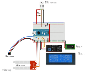
The SDA pin will be connected in our case to Arduino pin A4 and the SCL to pin A5, as shown at the above diagram.
Once the 4 wires are connected, the next thing to do it is to download and install the I2C Library for your LCD Display (it can be used for both, the 20X4 or for the 16X2 LCD):
https://github.com/fdebrabander/Arduino-LiquidCrys…
Open and upload to your Arduino the “Hello World” example that it is included with the library, changing the default set-up (16×2) for our 20X4. The address 0x27 worked fine in my case:
#include <Wire.h>
#include <LiquidCrystal_I2C.h>

// Set the LCD address to 0x27 for a 20 chars and 4 line display
LiquidCrystal_I2C lcd(0x27, 20, 4);

void setup()
{
	// initialize the LCD
	lcd.begin();

	// Turn on the blacklight and print a message.
	lcd.backlight();
	lcd.print("Hello, world!");
}

void loop()
{
	// Do nothing here...
}
Note: If you are not sure about your LCD I2C address, a simple I2C scan of your HW will show if there are I2C devices working properly and its address. The code can be found here: http://playground.arduino.cc/Main/I2cScanner

In my case, I run the program and got at Serial Monitor:
Scanning…
I2C device found at address 0x27 !
done
Let’s incorporate the LCD on our last code, so we can see the sensors readings at LCD:
1.4: Actuators and buttons for local control
Actuators
So far, we can read the data from sensors and display them at Serial monitor and LCD. It is time to do something with such data. Let’s think about the actuators!
As discussed at introduction, our final goal here is to take care of a tomato plantation, for example. With the data provide by sensors, we will know the air temperature and humidity, the luminosity and the most important how “dry” the soil where the plantation are. With those data in hand, our program should calculate if would be necessary to irrigate the plantation, turning on a Water Pump or to turn on an electric lamp to provide the appropriate heat to the crop. for that, we will use small 5V Relay Modules for Pump and Lamp activation. The Relay Module diagram circuit can be seen above.
Some modules have as inputs “G”, “V”, “S” or “S”, “-“, “+” or “In”, Vcc”, “GND”, etc.

Looking at the diagram, depending of your Relay Module, you must connect:
- Arduino 5V ==> “V” or “+”, or “Vcc”
- Arduino GND ==> “G” or “-” or “GND”
- Arduino OUT ==> “S” or “In” (in our case should be D10 for Pump and D8 for Lamp)
Usually you will see as output, 3 Pins: “NO”, “Ref”, NC”, that are: “Normal Open”, Reference and “Normal Closed”. We will use the pair: NO and Ref (center). At the above diagram, “NO” is the terminal to connect to “Live Mains” or the live positive of the Power Source (12VDC for Pump and 220VAC for Lamp). The “Ref” will be connected to Pump or Lamp as shown at above diagram. To know more about relays, visit: “Controlling Power With Arduino“.
Together with the relays, optionally 2 LEDs can be used to show if the relays are ON or OFF:
- LED Red: Pump
- LED Green: Lamp
For testing, it is great to have the LEDs on your BreadBord, but for a final project, you can take them out to save energy or maybe to use a different digital outputs for LEDs and Relays. They worked together, but will drive a reasonable amount of current from the Arduino (you will realize a drop of brightness at the LCD). Anyway for the final assembly and testing we will discuss a lot of considerations regarding energy savings.

Buttons
Based on the readings of sensors, an operator could be also decide manually control the Pump and/or Lamp. For that, two push-buttons will be incorporate to the project. They will work on a “toggle” mode: If an actuator is “ON”, pressing the button will “Turn-OFF” it and vice versa. The button’s logic will be “normally closed”, what means that Arduino Input will be constantly “HIGH”. Pressing the button, a “LOW” will be applied at the specific Arduino pin (please see the above block diagram).
Same we did with sensors, anytime that we will run the loop(), a functionreadLocalCmd() will be executed. This function will read each button, updating the status of actuators variables (pumpSatus and lampStatus). Note that the function type debounce(pin) is called instead a direct digitalRead (pin). This is to prevent false readings from the pushbutton. If you want to learn more about debouncing, please see this Debouncing Tutorial.
/****************************************************************
* Read local commands (Pump and Lamp buttons are normally "HIGH"):
****************************************************************/
void readLocalCmd()
{
  int digiValue = debounce(PUMP_ON);
  if (!digiValue)
  {
    pumpStatus = !pumpStatus;
    showDataLCD();
    aplyCmd();
  }

  digiValue = debounce(LAMP_ON);
  if (!digiValue)
  {
    lampStatus = !lampStatus;
    showDataLCD();
    aplyCmd();
  }
}
In the case where a button is pressed, another function will be called:aplyCmd(). And as the name says, will apply the correspondent command, turning the actuators ON or OFF:
/***************************************************
* Receive Commands and act on actuators
****************************************************/
void aplyCmd()
{
    if (pumpStatus == 1) digitalWrite(PUMP_PIN, HIGH);
    if (pumpStatus == 0) digitalWrite(PUMP_PIN, LOW);

    if (lampStatus == 1) digitalWrite(LAMP_PIN, HIGH);
    if (lampStatus == 0) digitalWrite(LAMP_PIN, LOW);
}
Code considerations
When we think about the 4 big “group of tasks” so far:
- Read sensors
- read buttons (local Command)
- Act on Pump/Lamp
- Display all Data
We will realize that the the timing when we should perform such tasks are not necessarily the same. For example, to read the Temperature and Humidity data from DHT 22, we will need to wait at least 2 seconds between mesure, but minutes are OK. For Soil Moisture sensor, as less measurements we do, better (due probe corrosion generate by electrolise) and last but not least, daylight will not vary instantly. But when we think about the actuators, as soon we press a button, we would like (and possibly need) a quick reaction.
So, the last instruction before the end of setup() will be the timer initialization using the “millis()” function instead of spreading a lot of delays around the full code:
startTiming = millis(); // starting the “program clock”
During the loop (), the first instruction will be to increment the variablestartTimingwith a real timing account.
elapsedTime = millis()-startTiming;
After that we will read the button status using the function readLocalCmd().This reading will happen any time that the program do the loop().
readLocalCmd(); //Read local button status
Regarding the Sensors, we will do the reading any 5 seconds for example and not at every loop:
if (elapsedTime > (5000))
{
readSensors();
printData();
startTiming = millis();
}
Bellow we can see the complete code for testing our “local Station”
1.5: Playing with a real Soil Moisture Sensor
You can skip this step if you want, but I think that would be interesting go a little deeper with this simple but key sensor. As briefly explained previously at step , a Soil Moisture Sensor is a simple “resistive voltage divider”.
Saying that, we can construct a very simple sensor using two metal probes like galvanized nails, pins or bolts. Above you can see the one that I create using simple material. The first sensor was built only with the two bolts connected with two wires (black/red).

As described on step 2, the “R1” is the “soil resistance” (not the best scientific term, but it’s OK). Taking 3 sample soil moisture samples for analysis, we can measure the R1 value using a multimeter as shown in the photo:

- Dry: R1 = > 20 Kohm (aprox)
- Humid: R1 = 4K to 6Kohm (aprox.)
- Wet: R1 = >1Kohm (aprox)
R2 it is the physical resistor that we will connect to complete the Voltage Divider (We will start with a 10K potentiometer for set-up). Calculating Vin at Arduino A1, proportionally to VCC, we would get the equation:
Vin = R2/(R1+R2)*VCC or Vin/VCC = 10K/(R1 + 10K)*100 [%]
Using the real values measured with the multimeter, we can anticipate that the results should be:
- Dry: 10K/30K*100 ==> < 30%
- Humid: 10K/15K*100 ==> ~ 67%
- Wet: 10K/11K*100 ==> > 90%

Making the connections at Arduino and running the code developed so far, we got as result:
- Dry: 13%
- Humid: 62%
- Wet: 85%
Of course because I moved the position of sensors, R1 changed BUT what really matters is the range of variation and not the absolute value. The sensor will be used for 3 states:
- Wet: Over 60% (no watering at all)
- Target Humid: Between 40 and 60% (Where we want to work) and
- Dry: Bellow 30% (need turn on the pump to increase the humidity)
As you can see using R2 as 10K worked fine, so we can take out the potentiometer and add a fixed resistor to our Soil Moisture Sensor.
One thing that I realized testing the sensors is that doing measurements often, will introduce an error on the readings, because the sensor also has a behavior as a “capacitor”. Once we “energize” the sensor for a data single capture we need wait a reasonable time even after we cut off the Sensor Power supply to “discharge the sensor”. Reverting the current will help, but it is not enough.
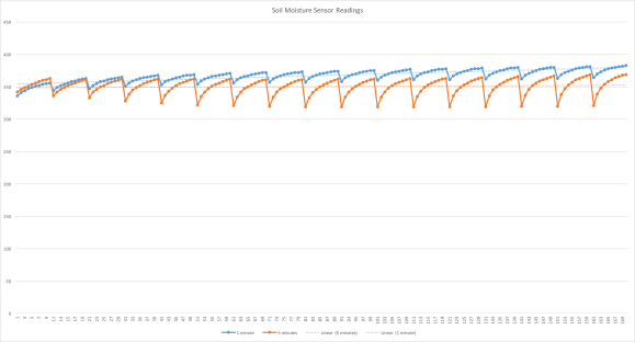
The above graphics show 2 set of measurements:
- Blue line: A cycle of 10 measurements with 1 seconds between samples and with 1 minute between cycles
- Orange Line: A cycle of 10 measurements with 1 seconds between samples and with 5 minutes between cycles
With 1 second interval, each new sample will be increasing significantly. Waiting 1 minute after cut off power will decrease the “storage voltage effect”, but will not eliminate it and the residual value will be added to next measurement. Increasing the interval of cycles to 5min for example will all most eliminate the error.
Based on the above results, the final code should not take samples with a frequency less than 10min.
The video bellow, show the tests with the sensor:
1.6: Changing the code to accommodate real measurements and final HW
As we could see at last step, we will need wait long cycles between Soil Moisture sensor measurements. It is Ok, for our automatic needs, but for manual operation we will not want to “wait” 10, 15 or more for a sensor measurements. So, we will introduce a 3rd push button to our project that will display the actual sensor data any time that we want, independent of the the timing of the automatic readings.

We will use the digital pin D17 (the same as A3) for the Push-Button and also introduce a “warning LED” (the yellow one at photo) connected to Pin 13. It will be “Light ON” when the sensors are been updating. Bellow the changed readLocal function:
/****************************************************************
* Read local commands (Pump and Lamp buttons are normally "HIGH"):
****************************************************************/
void readLocalCmd()
{
  int digiValue = debounce(PUMP_ON);
  if (!digiValue)
  {
    pumpStatus = !pumpStatus;
    showDataLCD();
    aplyCmd();
  }

  digiValue = debounce(LAMP_ON);
  if (!digiValue)
  {
    lampStatus = !lampStatus;
    showDataLCD();
    aplyCmd();
  }

  digiValue = debounce(SENSORS_READ);
  if (!digiValue)
  {
    digitalWrite(YELLOW_LED, HIGH);
    lcd.setCursor (0,0);
    lcd.print("< Updating Sensors >");
    readSensors();
    digitalWrite(YELLOW_LED, LOW);
  }
}
Another consideration is the introduction of a second Soil Moisture Sensor. On our final project, if fact we will use at 2 sensors in the plantation area so we can get 2 soils moisture readings at different locations. We will use the average of those reading in the final code to decide when to turn on the pump for example.
The Sensor “VCC and GND” will be the same (D7 and D6 respectively) and we will use the A2 for the second sensor. For simplicity, if only one sensor is used, the default is A1 and the code should ignore the A2 reading (a variable must be settle-up during Set-up). The number of samples of each cycle will be defined by variable “numSamplesSMS”. In principle only one is enough here, taking in consideration that as much reading we do on a short time will introduce errors due the capacitance effect. If you start to see errors on the reading, maybe extra sampleas should be taking.
Bellow the new Soil Moisture Sensor Function:
/***************************************************
* Capture soil Moisture data
****************************************************/
int getSoilMoist()
{
  int i = 0;
  int anaValue1 = 0;
  int anaValue2 = 0;
  for(i = 0; i < numSamplesSMS; i++) // // "numSamplesSMS" defines number of samples of each reading cycle
  {
    digitalWrite(SMS_VCC,LOW);   // drive a current through the divider in one direction
    digitalWrite(SMS_GND,HIGH);
    delay(500);   // wait a moment for capacitance effects to settle
    anaValue1 += analogRead(SOIL_MOIST_1_PIN);
    delay(500);   // wait a moment for ADC settle-up
    anaValue2 += analogRead(SOIL_MOIST_2_PIN);

    digitalWrite(SMS_VCC,HIGH);   // reverse the current
    digitalWrite(SMS_GND,LOW);
    delay(1000);   // give as much time in 'reverse' as in 'forward'
    digitalWrite(SMS_VCC,LOW);   // stop the current
    //delay (3000);
  }

  anaValue1 = anaValue1/(i);
  anaValue2 = anaValue2/(i);
  if (numSM == 2) anaValue1 = (anaValue1+anaValue2)/2; // "numSM" variable, defines number of moisture sensors that are connected

  anaValue1 = map(anaValue1, 1015, 3, 0, 100); //1015:0 (en el air) ==> 003:100% (poniendo un "short circuit)
  Serial.println(anaValue1);
  return anaValue1;
}

The above diagrams show the complete connections for the Local Control Station HW
1.7: It’s show time!
 At this point we have all HW in place and almost all SW done. What is missing is the “logic” allowing our system to really perform the task of irrigating the plantation automatically! We need to include some “neurons” to our brain!
As discussed before, let’s define the initial range where the Sensors will work. Those values should be changed using better practical values to be founded later on the real plantation:
Soil Moisture:
- “WET”: Over 60% (no watering at all)
- “Target Humid”: Between 40% and 60% (Where we want to work) and
- “DRY”: Bellow 40% (need turn on the pump to increase the humidity)
Temperature:
- COLD: Bellow 15oC (Turn-On the Light/Heat*)
- Optimum: between 20oC and 25oC
- HOT: Over 25oC (Do not Turn-On the Light/Heat)
Light:
- DARK (night): Bellow 40% (do not turn-on the Pump)
- LIGHT (day): Over 40%
(*) You can optionally test special Hydroponic Plant Grow LED Lights system. Those LED lamps can be used for both, to help faster growth due its special light frequency and also provide heat in case of low temperature.
You must have in mind that each type of seeds has a optimum range of temperature where it will grow faster. For example for Tomatos the minimum time for seeds to germinate will be 6 days on temperatures between 20 and 25 oC, going up for temperatures lower or higher than that:
- Temperature: degrees (oC): 10 15 20 25 30 35
- Time for Germination (days): 43 14 8 6 6 9
You can check more information about this relationship (Temp/Germination days) here: The effect of soil temperature on seeds germination
Having this 4 reading (Temperature, Humidity, Soil Moisture and Light), we can have a matrix defining where we want that our tomatos grow:
So, let’s remember our sensor variables and define some new definitions:
To be used by DHT Sensor
- int tempDHT;
- int HOT_TEMP = 25;
- int COLD_TEMP = 15;
To be used by LDR Sensor
- int lumen;
- int DARK_LIGHT = 40;
To be used by SM Sensor
- int soilMoist;
- int DRY_SOIL = 40;
- int WET_SOIL = 60;
Based on the above definitions, let’s think about some key assumptions:
- If it’s DRY ==> PUMP = ON ==> during the day
- If it’s DRY ==> PUMP = OFF ==> during the night: DARK (Tomatos do not like to receive water at night)
- If it’s COLD ==> LAMP = ON
- If it’s COLD ==> LAMP = OFF ==> if the soil is WET (to protect the root)
In this first part of project we will keep it simple and will not explore all possible combinations and the role of Air humidity on the equation. We will explore a more complex combination of sensors results on the 3rd part of this project, when we will apply the ArduFarmBot on a real plantation.
The Code:
Let’s create a new function that based on sensors reading, will deal automatically with actuators, turning on/off the Pump and Lamp:autoControlPlantation(). This function as shown bellow, will be called on every Cycle of Sensors readings:
void loop()
{
  // Start timer for measurements
  elapsedTime = millis()-startTiming;

  readLocalCmd(); //Read local button status
  showDataLCD();

  if (elapsedTime > (sampleTimingSeconds*1000))
  {
    readSensors();
    autoControlPlantation();
    startTiming = millis();
  }
}
The function will have 2 main tasks:
- Pump Control
- Lamp Control
The Pump control segment will use a new variable: “soilMoistAlert“.
//--------------------------------- PUMP ------//
  if (soilMoist < DRY_SOIL && lumen > DARK_LIGHT)
  {
    if (soilMoistAlert == HIGH)
    {
      soilMoistAlert = LOW;
      turnPumpOn();
    }
    else soilMoistAlert = HIGH;
  }
  else soilMoistAlert = LOW;
This variable will be used to avoid “false true”. So, if we get a true in the test: soilMoist < DRY_SOIL and that it is not during the night (lumen > DARK_LIGHT), we will not immediately turn on the Pump, but instead we will wait the next cycle to verify if the “soil is really dry”. If the result is a “yes” (get a “true” for answer twice), the function turnPumpOn () will be called:
/***************************************************
* TurnPumOn
****************************************************/
void turnPumpOn()
{
  digitalWrite(PUMP_PIN, HIGH);
  pumpStatus = 1;
  showDataLCD();
  delay (timePumpOn*1000);
  digitalWrite(PUMP_PIN, LOW);
  pumpStatus = 0;
  showDataLCD();
}
The Pump should be On for a fixed amount of time, defined by the variable:“timePumpOn” in seconds.
Note that we also changed the function that display data on LCD, so the status of the Pump now will be:
- “0”: Pump OFF (pumpStatus = 0; and soilMoistAlert = 0;)
- “X”: Pump in alert (pumpStatus = 0: and soilMoistAlert = 1;)
- “1”: Pump ON (pumpStatus = 1; and soilMoistAlert = 0;)
  lcd.print("Pump: ");
  if (soilMoistAlert  == 1) lcd.print ("X");
  else lcd.print(pumpStatus);
The same principle will be applied to Lamp control, but now a “Low Temperature” will be used to trigger the Lamp instead of “Dry soil” and if it is not “too wet”. Bellow the complete function: autoControlPlantation():
/***************************************************
* Automatically Control the Plantation based on sensors reading
****************************************************/
void autoControlPlantation()
{
//--------------------------------- PUMP ------//
  if (soilMoist < DRY_SOIL && lumen > DARK_LIGHT)
  {
    if (soilMoistAlert == HIGH)
    {
      soilMoistAlert = LOW;
      turnPumpOn();
    }
    else soilMoistAlert = HIGH;
  }
  else soilMoistAlert = LOW;

//--------------------------------- HEAT ------//
  if (tempDHT < COLD_TEMP && soilMoist < WET_SOIL)
  {
    if (tempLowAlert == HIGH)
    {
      tempLowAlert = LOW;
      digitalWrite(LAMP_PIN, HIGH);
      lampStatus = 1;
    }
    else tempLowAlert = HIGH;
  }
  else
  {
    tempLowAlert = LOW;
    digitalWrite(LAMP_PIN, LOW);
    lampStatus = 0;
  }
}
At this point the ArduFarmBot is fully functional in terms of HW and SW. The complete code can be found bellow:
1.8: Changing to a Small Form Factor

Once we have our prototype functional, let’s reassemble it on a better form using the “Funduino Nano Shield” and a plastic box for helping on external tests. The great advantage of a nano shield is that every component stays better assembled reducing bad contacts and noise. Also for external testing it is ease to have all main components on a small plastic box>
 If you are using the DHT stand alone, you must add a 10K resistor between VCC and Signal. If you are using a sensor module, the resistor is already included. For this new test I will use the DHT11 module that I have available. The result for our purpose is the same (only do not forget to change the line at the code to define the appropriate sensor that you will use: #define DHTTYPE DHT11).

Make 4 roles at the plastic box for LCD installation (I let it inside the box).
Make lateral  holes at the box so you can have the sensors out and have access inside for nano (power up via external Power Supply or SW updates) and connection of actuators (Pump/Lamp) with Relays outputs

Note that I used here the “1×4 Key Matrix Membrane Switch” as our control buttons.

You can decide the best way to fix the components at the box. I personally like the ordinary 3M stuff for easy fix/remove (see the above photo).
1.9: Funcional tests
Once everything is fixed on its place and de SW is uploaded, let’s do some functional tests simulating various sensor conditions in order to verify if all have been correctly assembled:
At normal light and temperature, introduce the the Soil Moister Sensor Probe on a cup with wet soil sample. Observe the Photo 1 (Temp is 22oC; Soil Hum. is 85% and Light is 80%). Nothing must happen. PUMP and LAMOP should be OFF (“0”).
 Keeping same light and temperature, let’s move the Soil probe to the cup with dry soil sample. At photo 2, you observe the the Pump was turned On (First went to “X” and after to “1” for a few seconds as defined on definitions).

Now as shown at Photo 3, the LDR was covered and the Light % went down to 19%. In this case spite of the fact that the soil is dry, the Pump will not turn-on, because our controller understand that it is at night.

In the photo 4, we put Ice at bottom of our box, close to the DHT Sensor. The temperature went down to 12oC and the Lamp was Turned-On.

And last but not least, on photo 5, we keep the ice but change the probe again to the wet soil sample. In this case spite of the fact that it is cold, according with our matrix, the lamp turned-off
1.10: “Test Drive”: Watering a Tomato plant with ArduFarmBot

For tests, I connected an electric pump that I have available. This will not be the final one, but can show how the project will work (So, do not care about the drops that you will see at below video).
1.11: The ArduFarmBot in action
Based on everything that we learned here, Maurício put the ArduFarmBot to really control his tomato plantation. Based on this real experience we should calibrate and define better the sensors and project parameters. The photos show the sequence of land preparation and introduction of the seeds. The real project will be explored in details on the 3rd phase of this project).

The below movie shows the ArduFarmBot in action:
Now it is only hope for a great salad!!!! Salut! 😉
1.12: Part 1 Conclusion

With this, we finish the first part of ArduFarmBot project. Here we create a Local Control Station, capturing information from a tomato plantation, as temperature, relative air humidity, luminosity and soil humidity. Based on those data, the ArduFarmBot decided automatically the right amount (and when) the plantation should receive heat and water. The local station, also allowed manual intervention of an operator in order to control the water pump and the electric lamp.
Now it is time to have our little friend connected with the Internet. On the ArduFarmBot – Part 2: “Remote Station” an IoT Implementation, we will implement an IoT approach were the “manual intervention” will be also possible remotely via Internet. On the part 2, the captured data will be send to a “Cloud Storage service” (in our case Thinkspeak.com). Also a dedicated website, the “Remote Control Page” will be monitoring and displaying those data in almost real time. This webpage will also permit the pump and lamp’s remote activation. Take a look there and enjoy!
The main files can be found on project depository: ArduFarmBot GitHub
As always, I hope this project can help others find their way in the exciting world of electronics, IoT and Robotics!
Saludos from the south of the world!
See you at my next post!
Thank you
Marcelo and Maurício


