
This is a simple tutorial, where we will explore how to read colors using an Arduino and sensors as the TCS 3200. The idea will be to detect an object color, displaying it on an LCD. This project will a component of a bigger project that will be a Robot Arm that will select a proper action based on object’s color.
The bellow block diagram shows the main components:

The video bellow shows the final project working:
Step 1: BoM
The bellow links and price are for reference only.
- Arduino Nano (US$ 8.00)
- TCS3200 Color Sensor Module (US$ 9.00)
- IIC/I2C/TWI 1602 Serial Blue Backlight LCD Module (US$ 8.00)
- Breadboard (US$ 2.00)
- Cables
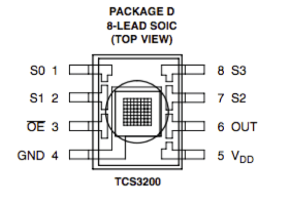
Step 2: The TSC 3200 Color Sensor

- Sixteen photodiodes have blue filters,
- 16 photodiodes have green filters,
- 16 photodiodes have red filters, and
- 16 photodiodes are clear with no filters.
Pins S2 and S3 are used to select which group of photodiodes (red, green, blue, clear) are active. Photodiodes are 110 μm x 110 μm in size and are on 134-μm centers.
The OE (Enable) should be connected to GND (LOW).
The Sensor as it si encapsulated should be powered between 2.7 and 5.5VDC. We will use the 5V Arduino output to power the sensor.
In order to properly use the sensor, we will install a small rubber ring to isolate the sensor from lateral light. I used hot glue to fix it.

Step 3: Connecting the HW

- Install the Arduino Nano at BreadBoard
- Connect the Nano 5V output and GND at both Power Rails
- Connect the TSC3200 Sensor as bellow:
- S0 ==> Nano pin D4
- S1 ==> Nano pin D5
- S2 ==> Nano pin D6
- S3 ==> Nano pin D7
- OUT ==> Nano Pin D8
- EN ==> GND
- VCC ==> +5V
- GND ==> GND
- Connect the I2C LCD 2/16 Serial Display:
- SDA ==> Nano Pin A4
- SCL ==> Nano Pin A5
Step 4: The Arduino Code

The first thing to define is the frequency scaling as defined at the table showed above. Pins S0 and S1 are used for that. Scaling the output frequency is useful to optimize the sensor readings for various frequency counters or microcontrollers. We will set S0 and S1, both in HIGH (100%):
  digitalWrite(s0,HIGH);
  digitalWrite(s1,HIGH);
Next thing to do is to select the color to be read by the photodiode (Red, Green, or Blue), we use the control pins S2 and S3 for that. As the photodiodes are connected in parallel, setting the S2 and S3 LOW and HIGH in different combinations allows you to select different photodiodes, as showed at above table.
    digitalWrite(s2, LOW);
    digitalWrite(s3, LOW);
    red = pulseIn(outPin, LOW); // Reading RED component of color

    digitalWrite(s2, HIGH);
    digitalWrite(s3, HIGH);
    grn = pulseIn(outPin, LOW); // Reading GREEN component of color

    digitalWrite(s2, LOW);
    digitalWrite(s3, HIGH);
    blu = pulseIn(outPin, LOW); // Reading BLUE component of color
On the final code, we will read a few times each one of the RGB components and take an average, so we can reduce the error if one of the readings are bad.
Once we have the 3 components (RGB), we must define what color is that. The way to do it to previously calibrate the project. You can use a known colored test paper or object and read the 3 components generated.
You can start with mine, changing the parameters for your level of light:
void getColor()
{
  readRGB();
       if (red > 8  && red < 18   &&  grn >  9 && grn < 19    &&  blu > 8  && blu < 16)   color = "WHITE";
  else if (red > 80 && red < 125  &&  grn > 90 && grn < 125   &&  blu > 80 && blu < 125)  color = "BLACK";
  else if (red > 12 && red < 30   &&  grn > 40 && grn < 70    &&  blu > 33 && blu < 70)   color = "RED";
  else if (red > 50 && red < 95   &&  grn > 35 && grn < 70    &&  blu > 45 && blu < 85)   color = "GREEN";
  else if (red > 10 && red < 20   &&  grn > 10 && grn < 25    &&  blu > 20 && blu < 38)   color = "YELLOW";
  else if (red > 65 && red < 125  &&  grn > 65 && grn < 115   &&  blu > 32 && blu < 65)   color = "BLUE";
  else  color = "NO_COLOR";
}
As you can see above I have predefined 6 colors: White, Black, Red, Green, Yellow, Blue. As the ambient light goes down, the parameters tend to go higher.
Inside the loop(), I define display the readings at LCD each 1 second.
The complete code can be found on my GitHub:
Step 5: Conclusion


