
This post is a continuation of ArduFarmBot: Part 1 – Controlling a Tomato Home Farm using Arduino and IoT
In the first part we create a local control station, capturing information from a tomato plantation, as temperature, relative air humidity, luminosity and soil humidity. Based on those data, the ArduFarmBot decided automatically the right amount (and when) the plantation should receive heat and water. The local station developed on the Part 1, also allowed manual intervention of an operator in order to control the water pump and the electric lamp. On this Part 2, we will implement an IoT approach were this “manual intervention” will be also possible remotely via Internet. The block diagram shows how we will do this.

Note that the captured data will be send to a “Cloud Storage service” (in our case Thinkspeak.com). Also a dedicated website, the “Remote Control Page” will be monitoring and displaying those data in almost real time. This webpage will also permit the pump and lamp’s remote activation.
Step 1: Bill of Material
- Arduino Nano – ($7.50)
- Temperature and Humidity Sensor DHT22 or DHT11 – ($3.66)
- Luminosity Sensor – AD-018 Photo resistor module. or any equivalent – ($0.71)
- 2X Soil Moisture Sensor – ($1.99) (Optional, can be DIY)
- LCD I2C 20X4 ($13.99)
- LEDs (1X) ($0.20)
- Esp8266 Serial Wifi Wireless Transceiver Module Esp-01 – ($5.96)
- Active Buzzer – Ky-12 or equivalent ($0.60)
- 2 X 5v Relay Module ($11.60)
- Jump wires (S1.00)
- 10KOhms resistor – ($0.03)
- 2.2K Ohms resistor – ($0.03)
- 1.0K Ohms resistor – ($0.03)
- 220 Ohms resistor – ($0.03)
- Arduino Nano Shield (“Funduino”) – ($7.28)
- Membrane keyboard (4 Keys) – ($6.65)
- Plastic Box
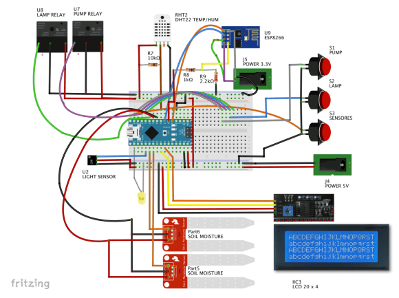
Step 2: Completing the Hardware
Starting from the Local Station developed on Part 1, the only additional HW needed is the ESP8266. The bellow block diagram, shows all Arduino and main components PIN connections.
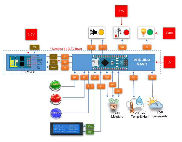
The only care that you must have is related with the voltage level. The ESP8266 works with 3.3V, so the Rx Pin that should not be connected directly to Nano Tx Pin (D3). A voltage level should be used. In our case, we will build a voltage divider to be used as a voltage level converter.


The electrical diagram here shows in more detail how to connect the ESP8266.
If you want to know more about the ESP8266, please see my Instructables (in english):
- The ESP8266 Part 1 – Serial WIFI Module for Arduino
- The ESP8266 Part 2 – Arduino Web Server
- The ESP8266 Part 3 – Triggering Arduino LEDs Remotely
Note that we are using the ESP8266 connected to Nano Pin 2 (Tx) and Pin 3 (Rx), using the library SoftSerial. If you want to “free” those digital pins, you can alternately use the Nano Serial pins 0 and 1. Only remember that you must disconnect them when uploading the code to Nano.
NOTE: If you want to connect the BUZZER, you should do it at pin D17 (same as pin A3). It is good to have a sound when you have a comm error. I used it during the test phase, leaving out at final project (the hw, but the code is prepared for that). It is up to you have it or not.
You can use the bellow code for testing and/or setup your ESP8266:

Step 3: The ESP8266 connection
To connect the ArduFarmBot to the Internet we will use the ESP8266, a simple, cheap and easy to program module for IoT projects. Once the module is installed, the first think to do is to to apply a “Reset” on its CH-PD Pin.
/***************************************************
* Reset funtion to accept communication
****************************************************/
void reset8266(void)
{
  pinMode(CH_PD, OUTPUT);
  digitalWrite(CH_PD, LOW);

  delay(300);
  digitalWrite(CH_PD, HIGH);
  Serial.print("8266 reset OK");
  lcd.clear();
  lcd.println("8266 reset OK       ");
}
After resetting, let’s connect it to your local network using your credentials (in the code, change: USERNAME and PASSWORD) and to initiate the module as a “STA: Station Mode” (CWMODE = 1):
/***************************************************
* Connect WiFi
****************************************************/
void connectWiFi(void)
{
  sendData("AT+RST\r\n", 2000, DEBUG); // reset
  sendData("AT+CWJAP=\"USERNAME\",\"PASSWORD\"\r\n", 2000, DEBUG); //Connect network
  delay(3000);
  sendData("AT+CWMODE=1\r\n", 1000, DEBUG);
  sendData("AT+CIFSR\r\n", 1000, DEBUG); // Show IP Adress
  lcd.clear();
  lcd.print("8266 Connected");
  Serial.println("8266 Connected");
}
To send data to ESP8266, the function sendData() was used:
/***************************************************
* Send AT commands to module
****************************************************/

String sendData(String command, const int timeout, boolean debug)
{
  String response = "";
  esp8266.print(command);
  long int time = millis();
  while ( (time + timeout) > millis())
  {
    while (esp8266.available())
    {
      // The esp has data so display its output to the serial window
      char c = esp8266.read(); // read the next character.
      response += c;
    }
  }
  if (debug)
  {
    Serial.print(response);
  }
  return response;
}
The above functions will be called during the “Setup Phase” of our Code. If everything were done correctly, you should see at Serial Monitor similar messages as bellow:

Step 4: Cloud Storage Data: The ThinkSpeak.com
All data captured by the ArduFarmBot will be uploaded to the cloud, using the free service of “ThinkSpeak.com”.
At the “Loop()” function (after we capture data with readSensors()), we will call an specific function to upload the captured data: updateDataThingSpeak();
/***************************************************
* Transmit data to thingspeak.com
****************************************************/
void updateDataThingSpeak(void)
{
  startThingSpeakCmd ();

  cmd = msg ;
  cmd += "&field1=";     //field 1 for DHT temperature
  cmd += tempDHT;
  cmd += "&field2=";    //field 2 for DHT humidity
  cmd += humDHT;
  cmd += "&field3=";    //field 3 for LDR luminosity
  cmd += lumen;
  cmd += "&field4=";    //field 4 for Soil Moisture data
  cmd += soilMoist;
  cmd += "&field5=";    //field 5 for PUMP Status
  cmd += pumpStatus;
  cmd += "&field6=";    //field 6 for LAMP Status
  cmd += lampStatus;
  cmd += "\r\n";

  sendThingSpeakCmd();
}
In order to send those data, the first thing to do is to start the communication with ThingSpeak. We will do this, using the finction: startThingSpeakCmd ();
/***************************************************
* Start communication with ThingSpeak.com
****************************************************/
void startThingSpeakCmd(void)
{
  cmd = "AT+CIPSTART=\"TCP\",\"";
  cmd += IP;
  cmd += "\",80";
  esp8266.println(cmd);
  delay(2000);
  if(esp8266.find("Error"))
  {
    Serial.println("ESP8266 START ERROR");
    return;
  }
  Serial.println("Thinkspeak Comm Started");
  cmd ="";
}
Once the channel is open with ThingSpeak and “cmd”string is assembled with the data, it is time to upload all of it the correspondent channel at ThingSpeak using the function: sendThingSpeakCmd();
/***************************************************
* Update channel ThingSpeak.com
****************************************************/
String sendThingSpeakCmd(void)
{
  esp8266.print("AT+CIPSEND=");
  esp8266.println(cmd.length());
  if(esp8266.find(">")){
    esp8266.print(cmd);
    Serial.println("");
    Serial.println("");
    Serial.println(cmd);
    delay(500);

    String messageBody = "";
    while (esp8266.available())
    {
      String line = esp8266.readStringUntil('\n');
      if (line.length() == 1)
      { //actual content starts after empty line (that has length 1)
        messageBody = esp8266.readStringUntil('\n');
        Serial.print("Message received: ");
        Serial.println(messageBody);
      }
    }
    return messageBody;
  }
  else{
    esp8266.println("AT+CIPCLOSE");
    Serial.println("ESP8266 CIPSEND ERROR: RESENDING"); //Resend...
    error=1;
    return "error";
  }
}
The above functions were based on a great and detailed tutorial developed by Michalis Vasilakis. For more details, please see his tutorial: Arduino IOT: Temperature and Humidity ( with ESP8266 WiFi).
The photo shows the ArduFarmBot channel at ThingSpeak.com:

Step 5: Commanding the actuators from the web

At this moment we are uploading all collected data and storing them at the cloud. This is very good and useful for a remote monitoring, but what happen if based on those data we also want to turn-on the Pump or the Lamp, independent of the the local automatic program? To do that, we will also need to “Download” data from the Cloud and command the controller to act based on those commands.
We will create specifics fields on our ThinkSpeak channel to command the actuators:
- Field 7:
- Data = 1 ==> PUMP should be Turn ON
- Data = 0 ==> PUMP should be Turn OFF
- Field 8:
- Data = 1 ==> LAMP should be Turn ON
- Data = 0 ==> LAMP should be Turn OFF
OK, but how to set up those fields directly at ThingSpeak? We can do it, for example writing a “PlugIn” directly at ThinksPeak, or we can use an external website to do it (this will be our choice). Anyway, on both cases a you should use a command like:
api.thingspeak.com/update?key=YOUR_WRITE_KEY&field7=1
With the above command, for example (and using your channel Write Key), you will write “1” at filed 7, what means that the PUMP should be turned on. You can easily test it, writing the above command-line at you browser, the correspondent field at your channel will be changed. As a return, the browser will show a white page with a single number on upper left corner, corresponding to the sequencial data entry in your channel.
So far, 50% of the work is done! Now you must read this “command” (data on the field), down at the local ArduFarmBot station.
The command to do this is shown bellow. It will get the last data that was written at the specific field (that in our case will be a “command”.
api.thingspeak.com/channels/CHANNEL_ID/fields/7/last
Same way as we did before, you can test the command-line, using your web browser. In this case, the browser will show you the data on that specific field. See the Photo above.

Returning to “earth”, let’s write a function that will read this “last field”:
/***************************************************
* Read data from field7 of thingspeak.com
****************************************************/
int readLastDataField7()
{
  startThingSpeakCmd ();

  // "GET /channels/CHANNEL_ID/fields/7/last";
  cmd = msgReadLastDataField7;
  cmd += "\r\n";

  String messageDown = sendThingSpeakCmd();
  Serial.print("Command received: ");
  Serial.println(messageDown[7]);

  int command = messageDown[7]-48;
  return command;
}
The above function will return the data on field 7 (“1” or “0”). A similar function should be written for Field 8.
Once we have the content of both fields, we should use them on a function that will command the actuators similarly how we did with the “manual command function”:
/***************************************************
* Receive Commands from thingSpeak.com
****************************************************/
void receiveCommands()
{
  field7Data = readLastDataField7();
  if (field7Data == 1)
  {
    digitalWrite(PUMP_PIN, HIGH);
    pumpStatus = 1;
    showDataLCD();
  }
  if (field7Data == 0)
  {
    digitalWrite(PUMP_PIN, LOW);
    pumpStatus = 0;
    showDataLCD();
  }

  delay (500);

  field8Data = readLastDataField8();
  if (field8Data == 1)
  {
    digitalWrite(LAMP_PIN, HIGH);
    lampStatus = 1;
    showDataLCD();
  }
  if (field8Data == 0)
  {
    digitalWrite(LAMP_PIN, LOW);
    lampStatus = 0;
    showDataLCD();
  }
  delay (500);
}
So, from now you can use the command-line in your browser to Turn On/Off the Pump and the Lamp remotely. The photo above shows how the received command will appear at your Serial monitor.
Another important consideration is the “coordination” between local and remote command. We must change the readLocalCmd() function to also update the Thinkspeak Field 7 and 8 respectivelly with Pump and lamp status (on their correspondent “IF statement”. See the complete code at end of this Instructable):
field7Data = pumpStatus;
field8Data = lampStatus;
Now “filed7Data” and “field8Data” are in sync with the webpage commands and also with local command actions when you press a button. So, let’s update the aplyCmd() function, that is the one responsible to turn on/off the actuators:
/***************************************************
* Receive Commands and act on actuators
****************************************************/
void aplyCmd()
{
  if (field7Data == 1) digitalWrite(PUMP_PIN, HIGH);
  if (field7Data == 0) digitalWrite(PUMP_PIN, LOW);

  if (field8Data == 1) digitalWrite(LAMP_PIN, HIGH);
  if (field8Data == 0) digitalWrite(LAMP_PIN, LOW);
}
When you start your tests you will realize that any command that you do manually at local or via web will be overcome by the automatic actions defined by the function autoControlPlantation(); At this point you should consider who will be the “boss”, having the last word! In our case here we will define the following:
- Every loop cycle, that it is almost “always”, we will look if a button is pressed
- Around every minute, we should do a “pooling” at ThinkSpeak and see if we have received an order from there.
- Around every 10 minutes, we will read the sensors, update the data on ThinkSpeak and more important take the automatic actions. Those actions will be taken independent of what were selected manually and will the one that will be kept.
You can change it, the way that you want. That is the good thing about using a programable processor for controlling things!
So, 2 timers will be used now, one for pooling the remote commands and another one for read the sensors (same one that we have used before:
long sampleTimingSeconds = 75; // ==> ******** Define Sample time in seconds to read sensores *********
int reverseElapsedTimeSeconds = 0;
long startTiming = 0;
long elapsedTime = 0;
long poolingRemoteCmdSeconds = 20; // ==> ******** Define Pooling time in seconds for new ThingSpeak commands *********
long startRemoteCmdTiming = 0;
long elapsedRemoteCmdTime = 0;
So, the loop() function should now be rewritten as bellow:
void loop()
{
  elapsedRemoteCmdTime = millis()-startRemoteCmdTiming;   // Start timer for pooling remote commands
  elapsedTime = millis()-startTiming;   // Start timer for measurements
  reverseElapsedTimeSeconds = round (sampleTimingSeconds - elapsedTime/1000);

  readLocalCmd(); //Read local button status
  showDataLCD();

  if (elapsedRemoteCmdTime > (poolingRemoteCmdSeconds*1000))
  {
    receiveCommands();
    updateDataThingSpeak();
    startRemoteCmdTiming = millis();
  }

  if (elapsedTime > (sampleTimingSeconds*1000))
  {
    readSensors();
    autoControlPlantation();
    updateDataThingSpeak();
    startTiming = millis();
  }
}
Step 6: Implementing a dedicated WebPage
At this point our ArduFarmBot is operational and can be controlled from the web. You can monitor the data on Thinkspeak site and also send commands using a browser, but of course this “web solution” can not be considered an “elegant” one! The best way to implement a full IoT solution is to develop a complete webpage that will display all data, also having buttons to activate the actuators.
I choose the Byethost, a free webhost, very easy and simple to handle your pages. I also used the opportunity to apply on this project, what I have learned on a fantastic on-line specialization at Coursera/University of Michigan: Learn to Design and Create Websites (Build a responsive and accessible web portfolio using HTML5, CSS3, and JavaScript).

I will not enter in details how to develop such page, once this is not the center purpose of this tutorial, but I will include here the HTML, CSS and JavaScript source codes. And once someone has interest on how I got the results, we can discuss it aside using the Comments Board at end of the project.
It is important to reinforce that this page does not works directly with the ArduFarmBot Local Control Station. What it is really doing is interacting with ThinkSpeak channel as bellow:
- Reading sensor data on fields 1, 2, 3, 4
- Reading actuator status on fields 5 and 6
- Writing data on fields 7 and 8
- Reading Local weather data from Yahoo services
The item 4 above is not really crucial for the project, but always are additional data available in case you want take some remote actions independent of what is going on locally with your tomato’s plantation. Other consideration is that you can for example, store those data on another ThingSpeak Channel and download it to your Arduino, showing weather data on local LCD display (I developed this on another cool project that worked fine! I leave it here as a suggestion to you).

Step 7: Return to the brain. A Sensor-Actuator Matrix approach

On the first part of this project, we have defined some preliminary considerations about how the actuators should act depending on sensors’ reading. We did only simple choice, but what will happen if we have a more complex situation? Several different conditions? What we will develop is a “Sensor – Actuator matrix approach”.
On a Matrix were defined for each sensor, its condition and how should be the output of actuators. The result can be saw on the Excel spreadsheet included bellow.

On the Excel file there are two spreadsheets. The table with a filter and a version were you can select multiple sensor conditions and see how the actuators will work due this selection.

Once the Matrix is defined, we must translated it to our code. An array of 18 lines and 10 columns was created to “copy” the conditions of Sensor-Actuator Matrix:
 //                       +---SOIL----+-LIGHT-+---TEMP---+---ACTUAT----+
 //                        SL  SM  SH  LL  LH  TL  TM  TH   Pump   Lamp
boolean SDf [18] [10] = {{  1,  0,  0,  0,  1,  0,  0,  1,    1,    0 },
                          { 1,  0,  0,  0,  1,  0,  1,  0,    1,    0 },
                          { 1,  0,  0,  0,  1,  1,  0,  0,    1,    1 },
                          { 1,  0,  0,  1,  0,  0,  0,  1,    1,    0 },
                          { 1,  0,  0,  1,  0,  0,  1,  0,    1,    0 },
                          { 1,  0,  0,  1,  0,  1,  0,  0,    0,    1 },
                          { 0,  1,  0,  0,  1,  0,  0,  1,    0,    0 },
                          { 0,  1,  0,  0,  1,  0,  1,  0,    0,    0 },
                          { 0,  1,  0,  0,  1,  1,  0,  0,    0,    1 },
                          { 0,  1,  0,  1,  0,  0,  0,  1,    0,    0 },
                          { 0,  1,  0,  1,  0,  0,  1,  0,    0,    1 },
                          { 0,  1,  0,  1,  0,  1,  0,  0,    0,    1 },
                          { 0,  0,  1,  0,  1,  0,  0,  1,    0,    0 },
                          { 0,  0,  1,  0,  1,  0,  1,  0,    0,    0 },
                          { 0,  0,  1,  0,  1,  1,  0,  0,    0,    1 },
                          { 0,  0,  1,  1,  0,  0,  0,  1,    0,    0 },
                          { 0,  0,  1,  1,  0,  0,  1,  0,    0,    1 },
                          { 0,  0,  1,  1,  0,  1,  0,  0,    0,    1 },
                         };
To work with the Matrix, we create a function defSensorStatus (). This function tests for each line if the condition of the 8 first columns are TRUE. If Yes, the condition of the last 2 columns are executed.
for example:
if (1 and 0 and 0 and 0 and 1 and 0 and 0 and 1) { pumpStatus = 1; lampStatus = 0}
else if (1 and 0 and 0 and 0 and 1 and 0 and 1 and 0) { pumpStatus = 1; lampStatus = 0}
and so on….
Inside the above function another array is created with the status of each sensor reading:
boolean snsSts[8]={0, 0, 0, 0, 0, 0, 0, 0}; // SL, SM, SH, LL, LH, TL, TM, TH
This variable array will be also used for LOG register.
Step 8: Code Optimization
During the process of developing the ArduFarmBot we realize that some changes on the original specification should be done:
Display:
The LCD display should be OFF by default and any time that a sensors reading is needed we can manually turn it “ON”. This condition was implemented on the code and the button “Sensors Read” should be used as in “toggle” mode to Turn ON/OFF the LCD at any time. Turn ON or OFF the display will update the sensors readings for displaying, but not used by ArduFarmBot on its regular functions.
Initial Setup:
When the ArduFarmBot is Turned ON (or reseted), the LCD will display the “Initial Set-up”. To start run the program, the button “Sensors” must be pressed. The Initial information (see the above photo) shown are:
- COLD Temperature (i.e. 12oC)
- DRY Soil Humidity (i.e. 30%)
- WET Soil Humidity (i.e. 60%)
- DARK light (i.e. 40%)
- P_ON Pump time be ON (i.e. 10s)
- SCAN Time to read sensors (i.e. 600s)
- SW_Vertion (i.e. 4.1)

Log Record:
For audit purposes, we have created a LOG with the readings and actuations of our ArduFarmBot. At every reading cycle, the function:storeDataLogEEPROM() is executed.
/***************************************************
* Storage of Log data at Arduino EEPROM
****************************************************/
void storeDataLogEEPROM(void)
{
  for (int i = 0; i<8; i++)
  {
    logData = logData + (snsSts[i])<< 1;
  }
  EEPROM.write (memoAddr, logData);
  memoAddr++;
  logData = 0;
  logData = logData + pumpStatus;
  logData = logData << 1;
  logData = logData + lampStatus;
  EEPROM.write (memoAddr, logData);
  EEPROM.write (0, memoAddr+1);
  logData = 0;
  if ((memoAddr+1) == 1023) memoAddr=1;
  else memoAddr++;
}
As commented in the last Step, what will be stored at the Arduino EEPROM is the content, bit a bit of the array snsSts[] plus Pump and Lamp status. You can see bellow, the LOG on Serial Monitor:

All the ArduFarmBot code were split in different files to be easer to understand. Note that 2 new files were added on this second part:
- communication.ino (ThingSpeak and ESP8266 specific funtions)
- stationCredentials.h (ThinkSpeak Channel ID and specific Keys for writing on the channel)
Last but not least, once the code ended with a reasonable size, we decided store the constant data in flash (program) memory instead of SRAM. For that, we use the PROGMEM keyword that is a variable modifier. For example, instead of using:
#define DHTPIN 5, we used:
const PROGMEM byte DHTPIN = 5;
The keyword PROGMEN tells the compiler “put this information into flash memory”, instead of into SRAM, where it would normally go. You must also include the library avr/pgmspace.h at main file of your code.
Another good procedure to reduce SRAM use is comment (or delete) all Serial.Print () lines that you used for debugging during development. You will realize that the code used for example to show the LOG at Serial Monitor will be commented on the bellow files.
Bellow you can find the complete ArduFarmBot Arduino code. Do not forget to change the dummy data on credentials.h with your Channel Id and Write Key. Also on communication.ino, use your real Username and password to connect the ESP 8266 at Internet.
Step 9: Conclusion

That’s all folks! ……For now!!
Soon we will publish the third and last part of our project that I hope will be a very good recipe of a organic tomato sauce pasta ;-). By the way, on the above photo you can see the first sighs of life on Mauricio’s plantation!

The main files can be found on project depository: ArduFarmBot GitHub
As always, I hope this project can help others find their way in the exciting world of electronics, IoT and Robotics! Saludos from the south of the world!
See you at my next post!
Thank you
Marcelo and Maurício


