
On my last tutorial, When IoT Meets AI: Home Automation With Alexa and NodeMCU we explored how to have voice activated devices as the Amazon Echo-Dot using a web service (like “Alexa”) can control “smart switches” on our homes. Here we will do the same, but instead of using Alexa, we will develop our own App on an Android smartphone to control locally (using buttons or voice), our home devices.
The block diagram shows what will be done in general:

and the movie shows the final project working:
Step 1: Bill of Material (BoM)
All values are referencial in USD
- NodeMCU ESP8266-12E ($8.79)
- Mini BreadBoard ($1.00)
- 400-point Experiment Breadboard Breadboard ($ 4.97)
- 4-Channel Relay Module ($8.49)
- LEDs (Red, Yellow, Blue and Green) ($1.00)
- 4 x Resistor (220 ohm)
- Male-Female Dupont Cables ($1.00)
- External 5V power Supply or battery
….. and of course, any Android Smartphone or Tablet!
Step 2: Connecting the NodeMCU to Local WiFi
#include <ESP8266WiFi.h>
WiFiClient client;
WiFiServer server(80);
const char* ssid = "YOUR SSID";
const char* password = "YOUR PASSWORD";

void setup()
{
  Serial.begin(115200);
  connectWiFi();
  server.begin();
}

void loop()
{
}

/* connecting WiFi */
void connectWiFi()
{
  Serial.println("Connecting to WIFI");
  WiFi.begin(ssid, password);
  while ((!(WiFi.status() == WL_CONNECTED)))
  {
    delay(300);
    Serial.print("..");
  }
  Serial.println("");
  Serial.println("WiFi connected");
  Serial.println("NodeMCU Local IP is : ");
  Serial.print((WiFi.localIP()));
}
On the Serial monitor you can see its IP Address:

Take note of it. We will need it to connect the Android App.
Step 3: Assembling the HW

We will use a 4 Channel relay module to control 4 LEDs, simulating 4 home devices.
Follow the below instructions:
Connect the Relays inputs with NodeMCU’s pins as bellow:
int relay1 = 14;
int relay2 = 15;
int relay3 = 3;
int relay4 = 1;
Our “smart devices” will be 4 color LEDs, as shown below:
- relay1 ==> LED Red
- relay2 ==> LED Yellow
- relay3 ==> LED Green
- relay4 ==> LED Blue
Our Android App will send a string that must be interpreted by our code to activate each one of the relays. Let’s define:
- Relay1:
- Turn-On: “r1on”;
- Turn-Off: “r1off”;
- Relay2:
- Turn-On: “r2on”;
- Turn-Off: “r2off”;
- Relay3:
- Turn-On: “r3on”;
- Turn-Off: “r3off”;
- Relay4:
- Turn-On: “r4on”;
- Turn-Off: “r4off”;
Let’s define a variable the will receive the commands (i) and the logic:
String command ="";
So, for example, If the Android App send as a command: “r1on”, Relay1 must be turn on.
if (command == "r1on")
{
  digitalWrite(relay1,LOW);
}
Note that the relays used in the project are activated with a LOW.
We will also define “group commands” to turn-on (“allon”) and turn-off (“alloff”) simultaneity all devices. For example, to Turn-On all of them:
    if (command == "allon")
    {
      digitalWrite(relay1,LOW);
      digitalWrite(relay2,LOW);
      digitalWrite(relay3,LOW);
      digitalWrite(relay4,LOW);
    }
Follow the above electrical diagram to finish the HW connection.
Download the complete code: Home_Automation_NodeMCU_Android_Voice_V2_EXT.ino from my GitHub.
Change the dummy wifi credentials, with your own:
const char* ssid = "YOUR SSID";
const char* password = "YOUR PASSWORD";
Upload the code to your NodeMCU and that’s it! You can check on Serial Monitor if the program is running, but, noting more. Let the program run for testing of your app on next step.
WARNING: When uploading a code ==> Power-off Relays
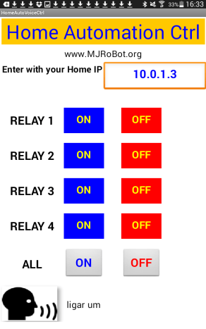
Step 4: The Android App: “Designer Tab”

We will use the MIT App Inventor to develop our Android App.
Main Components on Screen 1 (see above photo):
- User Interface:
- Input of IP Address (TextBox named “IP_Address”)
- 8 ON/OFF Buttons, one for each Relay:
- Relay_1_ON
- Relay_2_OFF
- etc
- 2 ON/OFF Buttons for All Devices:
- All_Devices_ON
- All_Devices_OFF
- Voice Input Button
- Voice_Input
- Non Visible Components:
- Web1
- SpeachRecognizer1
- TextToSpeach1
- Other:
- Text Box:
- Speach_To_Text
- Label:
- Comm_Status
- Text Box:
The App will look like this:
Step 5: The Android App: Buttons

We must at Blocks tabs, create 10 Buttons. All of them will follow the structure of the 2 shown at the photo.
Those 2 buttons blocks are for:
- Relay_1_ON. Click
- Relay_1_OFF.Click
They will be called when we “click” each one of those buttons. For example, when you click on Button Relay_1_ON, 3 actions will be performed:
- A command will be send on the format: http:/ip_address*/r1on
- An “echo” on the same format is expected
- A sound “message” will be read by the App: in the case: “Relé 1 ligado” (Relay 1 ON” in English)
* The IP_Address will be the one that you enter on Screen 1. The default is 10.1.0.3, so the real message would be: http:/10.0.1.3/r1on
You can use any message you want, or even took this block out. It is optional for the project.
Step 6: The Android App: the Voice Recognition

The above blocks show the voice recognition code for our App.
Note that, for any voice command entered, the result will be a lower case command. This will facilitate the voice recognition decoding on NodeMCU.
For example, if you want to “Turn ON” Relay 1, a word or sentence must be sent to be exactly recognized by NodeMCU code. I will send a command in Portuguese (my language), but you must send it on your own language (the one that is set-up on your Android device), and change the NodeMCU code properly
if (command == "r1on"  || command == "ligar 1"    || command == "ligar um")
{
  digitalWrite(relay1,LOW);
}
So, when I say “ligar um” (Turn-on one), the App will send for example: http:/10.0.1.3/ligar um and the NodeMCU will take “ligar um” and will put Relay 1 LOW, turning it.
Step 7: The Android App: Error Manipulation

If an error occur, the above block will write the error details on the last line (Comm_Status) of the App (if you generate it as Responsive).
Step 8: Final Test

You can create your App step by step as shown on the previous steps or upload my complete project (.aia) at MIT App Inventor modifying it for your needs.

Also If you do not have experience on developing Android apps, you can execute the .apk file directly on your Android device.
Both, the .aia and .apk files can be downloaded from my GitHub:
Step 9: Conclusion
As always, I hope this project can help others find their way in the exciting world of electronics and IoT!
Please visit my GitHub for updated files:
Home-Automation-with-Android-and-NodeMCU
Saludos from the south of the world!
See you at my next tutorial!
Thank you
Marcelo


